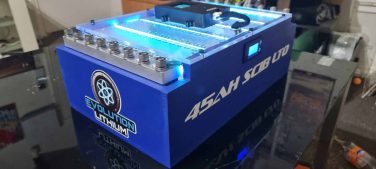


How to maintain a car audio lithium battery for stable voltage and long life
A car audio lithium battery does not need the same maintenance as a flooded lead-acid battery, but it still needs regular testing and inspection. The main jobs are to keep the charging voltage within the correct range for the battery chemistry, monitor individual cell behaviour, inspect every high-current connection, test voltage at the amplifier under load and prevent heat, vibration, moisture or parasitic drain from slowly damaging the system.
For an Evolution Lithium 6S SCiB LTO bank, the normal charging target is generally 15.6 to 15.9 volts unless the instructions supplied with the bank specify otherwise. The 16.8-volt figure comes from the maximum 2.8 volts per cell and should not be treated as the normal daily charging target. LiFePO4 batteries use different voltage limits, so an LTO charging setup must never be copied directly onto a LiFePO4 bank.
The most useful maintenance test is not a resting voltage reading. It is a controlled comparison between voltage at the battery and voltage at the amplifier while the system is playing under load. That test exposes weak grounds, loose lugs, damaged fuse holders, undersized cable and charging-system problems before they become expensive failures.
The practical maintenance rule: inspect the installation, confirm the charging voltage, watch the individual cells and test the complete circuit under a realistic load. Do not judge battery health from one dashboard voltage reading.
Start by identifying the battery chemistry
Battery care begins with knowing exactly what is installed. LTO, LiFePO4 and AGM batteries do not use the same voltage range or charging profile. A charger advertised simply as a “lithium charger” may still be wrong for the bank in your vehicle.
SCiB is not a separate chemistry from LTO. SCiB is Toshiba’s name for its lithium-ion cells that use lithium titanium oxide in the negative electrode. The correct description for an Evolution Lithium SCiB bank is therefore a SCiB LTO battery bank.
Before changing an alternator regulator, external charger or adjustable power supply, confirm:
- The cell chemistry and number of cells in series.
- The supplier’s normal charging range.
- The maximum permitted cell and bank voltage.
- The bank’s continuous current capability.
- The active balancer voltage range and connection order.
- The voltage limits of the amplifiers and other vehicle electronics.
For a broader breakdown of the differences, read the guide comparing LTO, AGM and LiFePO4 batteries for car audio.
Use a repeatable car audio battery maintenance schedule
A written schedule is more useful than checking the system only when the bass starts cutting out. High-current faults often develop gradually as vibration loosens hardware, moisture reaches exposed copper or repeated heat cycles affect a connection.
| Interval | Checks to complete |
|---|---|
| Before a demo or high-output session | Check bank voltage, charging voltage, active balancer display, fuse condition and visible cable connections. Confirm that no terminal or fuse holder is already warm. |
| Monthly | Inspect lugs, busbars, insulation, cable supports, mounting hardware and ground points. Look for discolouration, moisture, movement or corrosion. |
| Every three to six months | Perform a complete voltage-drop test under load. Compare voltage at the bank, fuse holder, distribution point and amplifier terminals. |
| After a wiring or charging-system change | Recheck polarity, fuse ratings, charging voltage, cell behaviour and amplifier input voltage before using full output. |
| Before long-term storage | Use the supplier’s recommended storage voltage, remove avoidable parasitic loads, protect the terminals and inspect the bank periodically. |
Measure voltage in the right places
A voltmeter connected near the dashboard cannot show everything happening in the rear electrical system. The battery, charging cable, fuse holders, grounds and amplifier connections all contribute to the voltage the amplifier actually receives.
1. Record the resting bank voltage
Turn the vehicle and audio system off, allow the bank to settle and measure directly across the main positive and negative terminals. Record the result rather than relying on memory.
Resting voltage is useful for tracking changes over time, but it is not a complete health test. LTO has a relatively flat discharge curve through much of its usable range, so a small voltage difference does not always translate neatly into an exact state of charge.
2. Measure the charging voltage at the bank
Start the vehicle with the audio system turned down and measure directly at the lithium bank. Repeat the test after the alternator has warmed up. Some charging systems begin at a higher voltage and then reduce output as temperature increases.
For an Evolution Lithium 6S SCiB LTO bank, the usual target is 15.6 to 15.9 volts. A system that remains below 14 volts will leave a large part of the useful LTO voltage range unavailable. Correct the charging system before expecting the battery bank alone to solve low-voltage performance.
See the detailed guide to raising vehicle charging voltage above 15 volts for an LTO battery bank.
3. Measure the battery and amplifier under load
Play familiar music or use a controlled test signal at a repeatable output level. Measure voltage at the battery terminals and then directly at the amplifier power and ground terminals.
If voltage remains stable at the battery but falls at the amplifier, the battery is not the first suspect. The loss is occurring through the positive cable, fuse holders, distribution hardware, ground return path or their connections.
If voltage falls sharply at both the battery and amplifier, investigate charging support, bank capacity, state of charge and the actual current demand from the amplifiers.
4. Perform a proper voltage-drop test
A voltage-drop test is performed while current is flowing. Measuring resistance with the circuit switched off can miss a connection that fails only when several hundred amps pass through it.
- Place one multimeter probe on the battery positive terminal and the other on the amplifier positive terminal.
- Run the audio system under a controlled load and record the displayed voltage loss.
- Repeat the test between the amplifier ground terminal and the battery negative terminal.
- Test smaller sections of the circuit to locate the loss, including each fuse holder, distribution block, cable and ground connection.
There is no useful reason to accept avoidable voltage loss in a high-current circuit. The goal is not to chase one universal number. It is to identify the part of the circuit producing a disproportionate loss compared with the rest of the installation.
For a complete diagnostic method, see how to measure and fix voltage drop in a car audio system.
Charge a 6S SCiB LTO battery correctly
Charging voltage has a direct effect on the usable energy and operating voltage of an LTO car audio bank. Charging too low leaves capacity unused. Charging too high reduces the margin for regulator error and cell imbalance.
Evolution Lithium’s normal guidance for a 6S SCiB LTO bank is:
- Preferred daily charging range: approximately 15.6 to 15.9 volts.
- Maximum cell voltage: 2.8 volts per cell.
- Maximum theoretical 6S bank voltage: 16.8 volts.
- Daily use: do not treat 16.8 volts as the normal target.
The complete system must also tolerate the selected voltage. Amplifiers, processors, relays, lighting circuits and factory vehicle electronics may have lower limits than the battery.
An external charger or adjustable power supply should be set for the exact battery configuration. Do not assume that an AGM, standard lithium-ion or LiFePO4 profile is safe for LTO. More detail is available in the guide to charging an SCiB LTO battery bank correctly.
Do not raise charging voltage to compensate for bad wiring. Fix voltage drop, weak grounds and alternator output first. Increasing regulator voltage can hide the symptom while the high-resistance connection continues producing heat.
Monitor individual cells and active balancing
Total bank voltage can appear normal even when one cell is behaving differently from the others. Individual cell readings show whether the bank is charging and discharging evenly.
Check the cells at comparable states of charge and under similar conditions. Look for patterns rather than reacting to one small difference:
- One cell repeatedly reaches the upper voltage first during charging.
- One cell falls faster than the others under load.
- The cell spread continues increasing after balancing.
- A cell reading changes when a busbar or sense-wire connection is moved.
- The same cell behaves differently at every test.
An active balancer moves energy between cells to reduce imbalance. It cannot repair a damaged cell, loose busbar, faulty sense lead or poor terminal connection. A bank that continually moves out of balance needs diagnosis rather than a more powerful balancing unit.
Evolution Lithium supplies a 6S active balancer for LTO car audio battery banks where active balancing is required.
Inspect cables, fuse holders and grounds
Many apparent battery problems begin elsewhere in the electrical system. A loose lug, contaminated ground or damaged fuse holder can restrict current, create heat and produce a large voltage drop during bass transients.
Check every high-current termination
Disconnect and isolate the bank before working around exposed conductors. Inspect each lug, busbar and terminal for:
- Loose hardware or signs that the lug has moved.
- Darkened copper, melted plastic or heat-damaged insulation.
- Corrosion between the lug and contact surface.
- Strands pulling out of a crimped terminal.
- Cracked heat-shrink or exposed conductor.
- Incorrectly stacked lugs that prevent flat contact.
Tighten hardware to the specification for the cell, busbar or terminal. More force is not automatically better. Excessive torque can damage threads, distort terminals or place stress on the cell casing.
Inspect fuse protection
The fuse protects the cable from excessive current after a short circuit or major fault. Its rating should be based on the cable and installation, not selected simply because the amplifier is large.
Check that each positive conductor leaving the bank is fused close to its source. Inspect the fuse element, fasteners and contact surfaces. A fuse can remain electrically connected while a poor contact around it creates significant heat and voltage loss.
The installation process is covered in more detail in how to wire an LTO battery bank safely in a car.
Test the complete ground return path
A short ground cable is not automatically a good ground. The current must return through the chassis, body joins, factory bonding straps and alternator case before it reaches the charging source.
Ground points should use clean structural metal, correctly crimped lugs and secure hardware. Protect the completed connection from corrosion without placing grease or coating between the electrical contact surfaces.
Follow the full guide to proper grounding techniques for high-current car audio systems.
Control heat, vibration and contamination
Evolution Lithium recommends installing high-current lithium battery banks in the boot or rear cabin rather than under the bonnet. The engine bay adds unnecessary heat, moisture, road contamination and vibration.
The bank should be held in a rigid mount that prevents movement during hard braking, cornering or a collision. Terminals and busbars must be protected from tools, loose metal objects and conductive debris.
During inspections, check for:
- Movement between the cells and mounting frame.
- Cracked brackets or loose fasteners.
- Cable weight pulling sideways on terminals.
- Blocked airflow around the bank.
- Water tracks, condensation or damp carpet.
- Abnormal heat near one lug, fuse or busbar.
A warm cable or connection is evidence of energy being lost as heat. Stop the test and locate the resistance or excessive current instead of continuing to play the system.
For placement and mounting guidance, read how to install a lithium car audio battery for reliable performance.
Prevent parasitic drain during storage
Amplifiers, digital signal processors, relays, Bluetooth modules, voltage displays and poorly configured remote wiring can continue drawing current after the vehicle is switched off.
If the bank loses more voltage while parked than expected:
- Fully switch off the audio system and allow the vehicle modules to enter sleep mode.
- Measure key-off current using a suitable meter or current clamp.
- Remove or isolate audio-system fuses one circuit at a time.
- Identify the device or relay that remains energised.
- Correct the remote turn-on or isolation arrangement.
For long storage periods, follow the battery supplier’s recommended storage voltage. Isolate avoidable loads where the installation allows it, protect exposed terminals and check the bank periodically.
Do not leave a bank discharged and assume the alternator will recover it during the next short drive. After a demanding demo, restore the bank using the vehicle charging system or a correctly configured external charger.
Diagnose the symptom before replacing the battery
Replacing a battery without testing the complete circuit can leave the original fault untouched. Use the pattern of the voltage readings to narrow down the cause.
| Symptom | Most likely area to test |
|---|---|
| Battery voltage is stable but amplifier voltage is low | Positive cable, fuse holders, distribution blocks, amplifier terminals and ground return path. |
| Voltage falls at both the battery and amplifier | State of charge, alternator output, charging voltage, bank capacity and actual amplifier current. |
| One cell rises or falls before the others | Cell condition, busbar connection, active balancer sense lead and repeated imbalance. |
| One lug or fuse holder becomes hot | Loose hardware, damaged contact surface, undersized component or excessive current. |
| Bank voltage falls while the vehicle is parked | Parasitic draw, remote turn-on wiring, relays, processors, displays and vehicle sleep behaviour. |
| Charging voltage starts correctly and then falls | Alternator temperature, regulator behaviour, belt slip, charging cable loss or alternator capacity. |
Use the detailed workflow for diagnosing alternator and charging problems in an LTO car audio system.
Know when routine maintenance is no longer enough
Stop using the bank and arrange a proper inspection when you find:
- A swollen, cracked, punctured or distorted cell casing.
- Leaking material or an unusual chemical smell.
- Burnt insulation, melted fuse holders or discoloured terminals.
- A cell that repeatedly reaches the voltage limit before the others.
- Abnormal heating during moderate charging or discharge.
- A loose cell terminal that cannot be tightened correctly.
- Damage caused by a collision, dropped tool or direct short circuit.
- A fuse that repeatedly opens without an identified cause.
Do not bypass the fuse, fit a larger fuse or continue charging in an attempt to confirm the fault. Isolate the system safely and inspect the battery, wiring and charging equipment.
Common car audio lithium battery maintenance mistakes
Using resting voltage as the only health test
A bank can show an acceptable resting voltage and still suffer from a weak connection, cell imbalance or poor performance under load. Test the system while current is flowing.
Assuming every lithium charger is compatible
LTO and LiFePO4 voltage limits are different. Verify the charger’s actual output and settings rather than relying on the label.
Increasing fuse size to stop nuisance failures
A fuse that opens repeatedly is reporting a fault, incorrect rating or excessive current. Increasing the fuse size without checking the cable can remove the protection the cable needs.
Mixing unmatched batteries or chemistries
Batteries with different voltage curves, age, internal resistance or state of charge will not necessarily share current evenly. Do not parallel unmatched banks without a properly engineered charging and isolation plan.
Expecting active balancing to repair a fault
Active balancing can correct normal differences between healthy cells. It cannot repair physical damage, a weak cell or a high-resistance connection.
Ignoring alternator support
A larger battery stores more energy, but it does not create charging current. The alternator must still replace the energy used by the audio system.
Use the car audio lithium battery and alternator calculator to compare amplifier demand, bank capability and charging support.
Frequently asked questions
How often should I check my car audio lithium battery?
Check the bank voltage, charging voltage and visible connections before demanding sessions. Complete a closer wiring and mounting inspection monthly, then perform a full voltage-drop test every three to six months or after any system change.
What is the correct charging voltage for a 6S SCiB LTO bank?
Evolution Lithium normally recommends approximately 15.6 to 15.9 volts for daily charging, unless the specific bank instructions state otherwise. A 6S bank reaches 16.8 volts at 2.8 volts per cell, but that is the maximum ceiling rather than the preferred everyday target.
Can I use a LiFePO4 charger on an LTO battery?
Not unless the charger can be manually configured to the exact voltage and current requirements of the LTO bank. A fixed LiFePO4 profile is designed for a different cell voltage and series configuration.
Does an LTO car audio battery require maintenance?
It does not require fluid checks