
How to Wire an LTO Battery Bank Safely in a Car
If you are asking how to wire an LTO (Lithium Titanate Oxide) battery bank safely in a car, the answer is to run a properly sized 6‑series pack in parallel with your starting battery, use high-current bolt-down fusing close to both positives, upgrade the Big 3 (alternator positive to battery positive, chassis ground to battery negative, and engine block ground to chassis), and verify your alternator regulation before first power-up. In short, how to wire an LTO battery bank safely in a car? Treat it like a second car audio battery with stricter standards: heavy copper conductors sized for peak current, solid ground strategy, a cell balancer (Evolution Lithium offers an integrated Heltec 5.5A 6S active balancer option) at the pack, a pre-charge step to avoid inrush arcing, and careful commissioning with a digital multimeter and clamp meter. When installed this way, an LTO (Lithium Titanate Oxide) SCiB (Super Charge ion Battery) bank can deliver the voltage stability that powerful amplifiers and SPL (Sound Pressure Level) builds demand and help reduce stress on vehicle electronics when properly installed.
Traditional lead-acid and AGM batteries can show greater voltage drop during high current demand. SCiB LTO banks suit car-audio use because their low internal resistance, fast charge acceptance and cycle life support a stable electrical system when the wiring and alternator are correctly matched. Evolution Lithium in NZ (New Zealand) hand-assembles custom SCiB (Super Charge ion Battery) banks and accessories that match real-world car audio needs. This guide answers the practical installer questions: cable size, fuse placement, alternator upgrade for car audio, grounding, pre-charge, and test procedures. Along the way you will see why LTO (Lithium Titanate Oxide) is a proven upgrade for lithium battery bank car audio reliability, what to watch for with modern smart alternators, and how to avoid the most common mistakes that cause voltage drop, noise, or equipment failure.
Prerequisites and Tools
Before you start, confirm you are comfortable working with high-current DC (Direct Current) systems. If not, consult a qualified installer. Gather these items and information so your job goes smoothly.
- Power budget: sum amplifier rated power and estimate current draw. Example: a 3,000 watt Class D amplifier at 80 percent efficiency draws roughly 260 amperes at 14.4 volts under full output.
- LTO (Lithium Titanate Oxide) bank: typically a 6‑series SCiB (Super Charge ion Battery) pack for 12‑volt systems, assembled with copper busbars and cell-level balance leads. Evolution Lithium sells configurable banks built from Toshiba SCiB LTO cells in multiple Ah formats and custom Ah sizes to match different installations.
- Protection and control: bolt-down high-current fuses for each positive close to the source, a main disconnect switch or contactor, and a cell balancer (for example the integrated Heltec 5.5A 6S active balancer option) rated for 6‑series.
- Conductors and terminations: 1/0 AWG (American Wire Gauge) or 2/0 AWG (American Wire Gauge) oxygen-free copper cable for long runs, tinned copper lugs, adhesive-lined heat shrink, and proper crimping tooling.
- Distribution hardware: copper busbars or quality distribution blocks, plus a secure, ventilated mount for the bank away from heat and moisture.
- Test equipment: digital multimeter, DC (Direct Current) clamp meter, and if available, an oscilloscope for ripple checks at the amplifier inputs.
- Pre-charge device: a resistor around 5 to 10 ohms at 25 watts or a purpose-built pre-charge device; some installers use an incandescent headlight bulb as an improvised option, but a commercially available pre-charge resistor/unit is recommended.
- Documentation: alternator voltage behavior, ECU (Engine Control Unit) or RVC (Regulated Voltage Control) details for your vehicle, and your amplifier manufacturer wiring guidance.
How the System Works
A 12‑volt car electrical system centers on the alternator and starting battery. Adding an LTO (Lithium Titanate Oxide) SCiB (Super Charge ion Battery) bank in parallel increases the system’s ability to supply large, fast current bursts while holding voltage near the alternator set point. The key is internal resistance. LTO (Lithium Titanate Oxide) cells exhibit very low resistance and high C‑rate capability, so they fill in the milliseconds of demand that cause lead-acid and AGM (Absorbed Glass Mat) batteries to sag. In daily driving, the alternator recharges the pack quickly, and because LTO (Lithium Titanate Oxide) accepts charge well at lower temperatures and partial states of charge, recovery after bass hits is rapid.
For most 12-volt car-audio systems, a 6-series SCiB LTO pack is the appropriate configuration. Each cell is 2.4V nominal, so a 6S bank is 14.4V nominal. Set charging from the cell specification and the measured terminal voltage; Evolution Lithium generally targets about 15.6–15.9V for 6S SCiB, with 16.8V as the absolute maximum. An active balancer helps keep the six series groups aligned. Correct wiring and low-resistance current paths help maintain amplifier voltage under load.
| Series Count | Nominal Pack Voltage | Preferred charge range | Typical Use in Vehicles |
|---|---|---|---|
| 5‑series LTO (Lithium Titanate Oxide) | 11.5 to 12.0 volts | 13.5 to 13.8 volts | Special cases with low alternator set points; less common for car audio |
| 6‑series LTO (Lithium Titanate Oxide) | 13.8 to 14.4 volts | 15.6 to 15.9 volts preferred; 16.8V absolute maximum | Recommended for most 12‑volt automotive audio systems |
| 7‑series LTO (Lithium Titanate Oxide) | 16.1 to 16.8 volts | 18.0 to 18.9 volts | Not for standard 12‑volt vehicles; specialty racing or 16‑volt audio only |
Why It Matters for High-Power Car Audio
High-discharge amplifiers demand hundreds of amperes during bass transients. A few tenths of a volt lost to cable resistance or battery sag equals real power left on the table. For example, a 0.5‑volt drop at 300 amperes is 150 watts of heat in the wiring instead of power to the subwoofers. LTO (Lithium Titanate Oxide) banks reduce this problem by providing both low internal resistance and high burst capability, which stabilizes voltage at the amplifier rails. For SPL (Sound Pressure Level) power systems, even a 0.2‑volt improvement can be the difference between a clean run and clipping or shutdown.
Real-world installers in NZ (New Zealand) and AU (Australia) report that LTO (Lithium Titanate Oxide) SCiB (Super Charge ion Battery) banks recharge fast between songs, hold voltage against dynamic loads, and weigh far less than equivalent lead-acid or AGM (Absorbed Glass Mat) stacks. Toshiba’s published SCiB (Super Charge ion Battery) data shows very long cycle life, with many implementations seeing over ten thousand cycles before significant capacity loss under moderate depth of discharge. Combined with a robust alternator upgrade for car audio and correct cable sizing, the result is fewer dimming lights, more consistent amplifier output, and less strain on the electrical system.
Practical Installation Considerations
- Choose a bank sized for both burst current and average recharge. Many builds use 10 to 20 ampere-hours of LTO (Lithium Titanate Oxide), with higher C‑rate modules for heavy SPL (Sound Pressure Level) use.
- Mount the pack in the boot/trunk or amplifier rack on a rigid tray, with insulating barriers and service access for fuses and the disconnect switch.
- Plan distribution so the LTO (Lithium Titanate Oxide) bank feeds a copper busbar, then short, equal-length runs to each amplifier input.
- Decide your ground strategy: a dedicated negative cable back to the front battery or clean, sanded chassis points reinforced with copper ground straps.
- Verify alternator regulation and charging profile. Some smart systems float lower at idle; a DC‑DC (Direct Current to Direct Current) booster or external regulator may be required for demanding builds.
Safety and Electrical Design Practices
- Fuse every positive within 200 millimetres of each battery positive post, both front and rear. Size the fuse to protect the cable’s ampacity, not the load’s rating.
- Use only quality copper cable. For long runs over three metres with more than 250 amperes expected, 2/0 AWG (American Wire Gauge) is usually justified.
- Route cables away from sharp edges and heat. Grommet all firewall penetrations.
- Include a pre-charge step any time the bank is disconnected or serviced to avoid inrush arcing at the connectors and switch gear.
- Balance cells regularly. A 6‑series active balancer (such as Evolution Lithium’s integrated Heltec 5.5A 6S active balancer option) prevents cell drift over time.
- Label everything and keep a schematic in the vehicle. Future you or a technician will thank you.
Step 1: Plan the System — How to wire an LTO battery bank safely in a car?
Start with the power math and system limits. List your amplifiers, note their rated power, efficiency, and the impedance they will see in real use. Estimate peak and sustained current draw, then consult your vehicle’s alternator rating. If the alternator cannot replenish the average draw during spirited listening, an alternator upgrade for car audio or a second alternator should be in your plan. Next, choose a 6‑series LTO (Lithium Titanate Oxide) SCiB (Super Charge ion Battery) configuration for most 12‑volt systems, and decide your target ampere-hours based on musical duty cycle. Evolution Lithium can assemble custom banks using 3 ampere-hour 75C, 10 ampere-hour 75C, or 20 ampere-hour 35C SCiB (Super Charge ion Battery) cells, letting you balance burst capability, mounting space, and budget.
Finally, document your protection scheme. Every positive conductor leaving a battery must be fused, and conductor size must match the expected current. Sketch a layout: front battery and alternator at the nose, heavy positive to the rear fuse, then LTO (Lithium Titanate Oxide) bank to a busbar and short runs to each amplifier. Mark grounds with equal attention. Decide up front whether you will run a dedicated negative cable to the front or rely on reinforced chassis grounds. If your vehicle has RVC (Regulated Voltage Control), note the voltages you observe at idle, cruise, and under electrical load to ensure the LTO (Lithium Titanate Oxide) bank will charge adequately.
| Cell Type | Typical C‑Rate | Use Case | Key Benefit |
|---|---|---|---|
| 3 Ah 75C SCiB (Super Charge ion Battery) | High burst capability | Compact daily systems and small SPL (Sound Pressure Level) builds | Very light and fast charging |
| 10 Ah 75C SCiB (Super Charge ion Battery) | Very high burst capability | Moderate to large monoblocks | Excellent voltage stability under peaks |
| 20 Ah 35C SCiB (Super Charge ion Battery) | High continuous and burst capability | Sustained output and SPL (Sound Pressure Level) demos | Great balance of capacity and footprint |
Step 2: Select Cable Sizes, Fuse Ratings, and Distribution
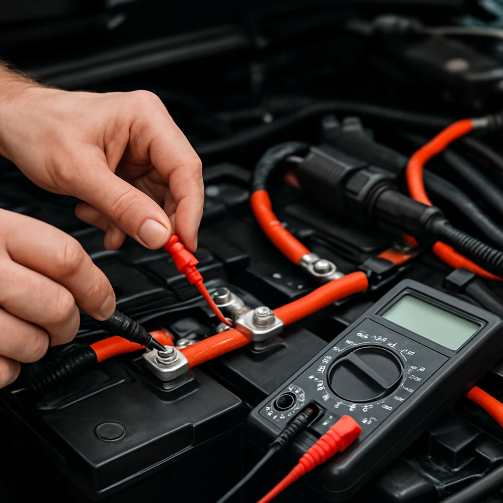
Choose cable sizes by allowable voltage drop and thermal limits. Long positive runs are the number one source of loss in lithium bank car audio installs. For a four metre run of 1/0 AWG (American Wire Gauge) copper at 300 amperes, expect about 0.39 volts drop, which wastes around 116 watts as heat. Upgrading to 2/0 AWG (American Wire Gauge) for the same run reduces drop to about 0.31 volts at 300 amperes, saving roughly 24 watts and tightening amplifier rail voltage. Size fuses to protect the smallest downstream cable, mounting each fuse within 200 millimetres of its source battery. For distribution, copper busbars keep connection resistance low and make it easy to land multiple amplifier inputs with equal length leads.
| Cable Size | Resistance per metre | Estimated Drop | Power Lost as Heat | Recommendation |
|---|---|---|---|---|
| 1/0 AWG (American Wire Gauge) | 0.000322 Ω/m | 0.39 V | 116 W | Usable, consider 2/0 AWG for heavy SPL (Sound Pressure Level) |
| 2/0 AWG (American Wire Gauge) | 0.000255 Ω/m | 0.31 V | 93 W | Preferred for long rear runs and 3 kW+ systems |
| 4 AWG (American Wire Gauge) | 0.000815 Ω/m | 0.98 V | 294 W | Too small for main battery-to-battery runs |
Step 3: Prepare the Vehicle Electrical — Big 3, Grounds, and Alternator
Execute the Big 3 (alternator positive to battery positive, chassis ground to battery negative, engine block ground to chassis) with copper equal to or larger than your main run. Clean paint off ground points to bare metal, use serrated washers, then seal with anti-oxidant compound and paint. If you plan chassis grounds for the rear, add copper ground straps between chassis points to reduce return path resistance. Measure voltage at idle and at 2,000 rpm with lights, blower, and defogger on to learn your alternator’s regulation window. Most car audio battery systems with LTO (Lithium Titanate Oxide) perform best when charging is 14.2 to 14.8 volts hot.
Modern vehicles with RVC (Regulated Voltage Control) may lower voltage at idle for fuel economy. If your alternator often sits below 13.8 volts, consider an alternator upgrade for car audio with a higher hot set point or an external regulator approved for your platform. In some cases a DC‑DC (Direct Current to Direct Current) booster can stabilize the charging bus to keep the 6‑series LTO (Lithium Titanate Oxide) bank happy, although many NZ (New Zealand) and AU (Australia) daily builds do fine with stock alternators plus LTO (Lithium Titanate Oxide) when the current budget is sensible.
Step 4: Assemble and Mount the LTO (Lithium Titanate Oxide) Bank
If you are using a pre-assembled Evolution Lithium SCiB (Super Charge ion Battery) bank, verify cell voltages are even, busbars are torqued, and balance leads are connected per documentation. For custom assemblies, arrange cells in a rigid frame, connect series busbars with correct polarity, and leave space for fusing, a disconnect and a correctly sized active balancer. Mount the bank low and secure, away from exhaust heat and moisture. Allow clearance for cable bend radii and fuse service.
Plan where the rear fuse will live. The most robust approach is a bolt-down high-current fuse mounted within 200 millimetres of the LTO (Lithium Titanate Oxide) positive post, feeding a short cable to a copper busbar or distribution block. If you expect to isolate the rear bank for service, include a manual disconnect switch or a contactor rated for the full short-circuit current, installed after the fuse. Keep the negative post protected with a terminal cover or insulating boot to prevent accidental shorts during cargo loading.
Step 5: Wire the Positive Side and Protect It
Crimp and heat-shrink your main positive cable from the front battery fuse to the rear fuse, then to the LTO (Lithium Titanate Oxide) bank positive. A high-quality hex or dieless crimper is essential for reliable, low-resistance terminations. Keep runs as straight and short as practical, support them with P‑clips, and avoid tight bends. At the front, add a fuse within 200 millimetres of the starting battery positive. At the rear, place the main fuse within 200 millimetres of the LTO (Lithium Titanate Oxide) positive. Then route a short, heavy positive from the bank to your copper busbar or distribution block, and from there to each amplifier with equal-length cables.
Positive Wiring Tips
- Stagger and label amplifier feeds to simplify troubleshooting and to know which fuse corresponds to which amplifier.
- Use lock washers and proper torque on all bolt-down fuse terminals and busbar connections. Re-torque after the first week of driving.
- Keep signal cables separated from power cables where possible to minimize induced noise at the amplifier inputs.
Step 6: Wire the Grounds and Verify Resistance
Your negative strategy can be either a dedicated negative cable back to the front battery or reinforced chassis grounds. A dedicated negative mirrors the positive path resistance and is the best practice for extreme SPL (Sound Pressure Level). If you use the chassis, belt-and-braces it: sand to bare metal, use large lugs and star washers, then test with a multimeter. Aim for less than a few milliohms between the rear ground and the front battery negative. Add copper ground straps between body, frame, and suspension points to lower return impedance. Finally, run short, equal-length negative cables from the busbar to each amplifier ground block.
Grounding Best Practices
- Do not mix multiple small grounds in different locations. Use a star ground back to a single point.
- Avoid painted or seam-welded areas. Thick, flat frame or chassis rails provide the lowest impedance.
- Measure voltage drop across the ground path during a bass hit. Anything more than a few tens of millivolts suggests you need more copper or better contact.
Step 7: Balance, Pre-Charge, and Make the First Connection
Before connecting the LTO (Lithium Titanate Oxide) bank to the vehicle, ensure all cell voltages are even. Connect your 6‑series balancer (for example, Evolution Lithium’s integrated Heltec 5.5A 6S active balancer option) and verify activity. To avoid inrush arcing that can pit switch contacts and lugs, pre-charge the system. With the front and rear fuses removed, bridge the positive path at the rear with a purpose-built pre-charge resistor or a commercially available pre-charge device (some installers use an incandescent headlight bulb as an improvised option) for 30 to 60 seconds. This charges amplifier capacitors and busbars gently. Then remove the pre-charge, install the rear fuse, and finally install the front fuse while observing for any abnormal current or heat.
After power-up, measure voltage at the front battery, at the LTO (Lithium Titanate Oxide) bank, and at the amplifier positive blocks. The difference between the front and rear readings at idle indicates static drop; under a quick 2 to 3 second bass burst at moderate volume, observe dynamic sag. Well-executed systems with 2/0 AWG (American Wire Gauge) runs commonly hold within 0.2 to 0.3 volts at several hundred amperes. If you see more, revisit cable size, grounds, and fuse contact quality.
Step 8: Commissioning, Monitoring, and Maintenance
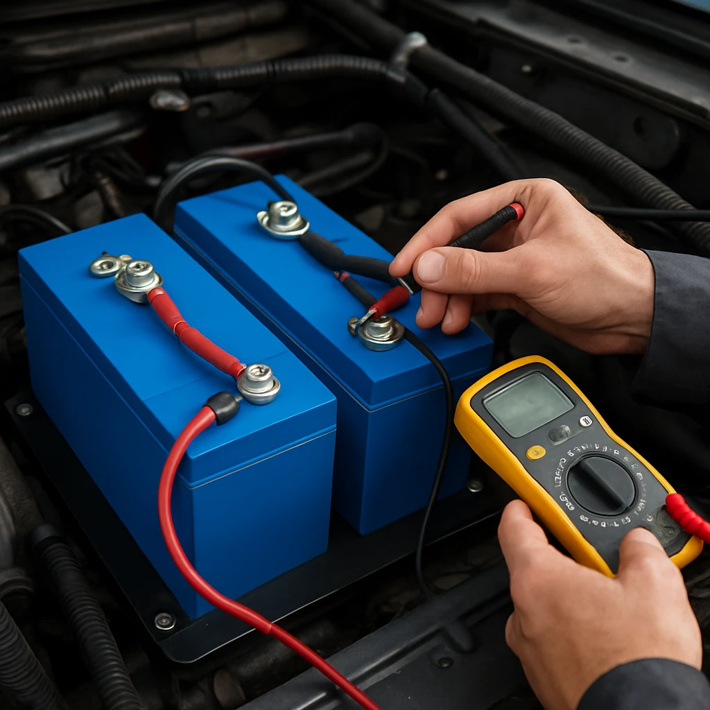
Play a familiar test track and monitor voltage at the amplifiers while gradually increasing volume. Listen for alternator whine or amplifier protection events, and check for warm lugs after five minutes of operation. Use a clamp meter to confirm expected current draw against your initial power budget. If your vehicle has RVC (Regulated Voltage Control), note whether the alternator drops into low voltage at idle. If so, a slightly higher idle speed or a regulator adjustment may help during demos. Over the first week, re-torque all terminations, inspect fuse blocks for discoloration, and confirm your balancer keeps cell voltages aligned.
For long-term care, keep the bank clean and dry, and schedule a quarterly inspection. LTO (Lithium Titanate Oxide) SCiB (Super Charge ion Battery) technology is robust and tolerant of rapid charge and discharge, with published data suggesting well over ten thousand cycles at moderate depth of discharge. Still, tidy wiring and periodic checks make the difference between a reliable, competition-worthy SPL (Sound Pressure Level) power system and a nuisance. When in doubt, ask Evolution Lithium for cell-level advice, as they hand-assemble units and can guide you on settings and service intervals specific to Toshiba SCiB (Super Charge ion Battery) cells.
Common Mistakes to Avoid
- Skipping fuses: every positive leaving any battery must be fused near the source. Do not rely on a single upstream fuse for multiple downstream cables.
- Under-sizing cable: long 4 AWG (American Wire Gauge) runs are not suitable for high-power lithium bank car audio. Use 1/0 AWG (American Wire Gauge) or 2/0 AWG (American Wire Gauge) for main runs.
- No pre-charge: connecting a fully charged LTO (Lithium Titanate Oxide) pack straight into empty amplifier capacitors can arc and damage lugs, switches, and fuses.
- Ignoring alternator behavior: smart alternators with low set points may not fully support a 6‑series LTO (Lithium Titanate Oxide) bank at idle without adjustments.
- Poor grounds: paint, seam welds, or thin sheet metal create high impedance. Reinforce and test.
- Unbalanced cells: running with no active balancer can let cells drift over time.
- Mounting near heat: batteries and fuses near exhausts or amplifiers without airflow suffer early failure.
Real-World Examples and Sizing Guidance
Consider a daily driver in NZ (New Zealand) with a 5,000 watt monoblock at 80 percent efficiency. At full clip, average draw is roughly 430 amperes, though music is dynamic. A 10 to 20 ampere-hour LTO (Lithium Titanate Oxide) SCiB (Super Charge ion Battery) bank with 2/0 AWG (American Wire Gauge) runs, front and rear bolt-down fuses, and a solid Big 3 has proven stable for many such builds, especially when the alternator is 220 amperes or higher hot. For demo-heavy SPL (Sound Pressure Level) applications with long sustained bass, moving to 20 ampere-hour or more provides extra voltage stability during back-to-back songs and quicker recovery.
| Amplifier Power | Estimated Average Current at 14.4 V | Suggested LTO (Lithium Titanate Oxide) Bank | Main Cable Recommendation |
|---|---|---|---|
| 2,000 watts total | 140 to 180 amperes | 6‑series, 10 Ah SCiB (Super Charge ion Battery) | 1/0 AWG (American Wire Gauge) |
| 5,000 watts total | 350 to 450 amperes | 6‑series, 10 to 20 Ah SCiB (Super Charge ion Battery) | 2/0 AWG (American Wire Gauge) |
| 10,000 watts total | 700 to 900 amperes | 6‑series, 20 Ah+ SCiB (Super Charge ion Battery), multiple parallel modules | Multiple 2/0 AWG (American Wire Gauge) or busbar trunking |
Suggested Images to Add
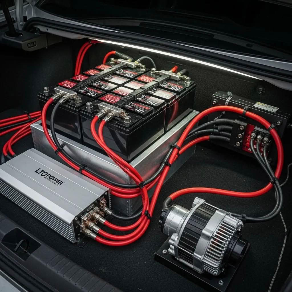
- LTO (Lithium Titanate Oxide) SCiB (Super Charge ion Battery) bank mounted on a tray with copper busbars and balance leads.
- Amplifier rack with distribution blocks and equal-length power and ground runs.
- Diagram of front-to-rear wiring showing fuses within 200 millimetres of each battery and the pre-charge location.
- Close-up of a properly prepared chassis ground with bare metal, star washer, and protective coating.
Why Choose Evolution Lithium for SCiB (Super Charge ion Battery) LTO (Lithium Titanate Oxide) Banks
Evolution Lithium focuses on car audio battery solutions built around genuine Toshiba SCiB (Super Charge ion Battery) cells. Their custom-built LTO (Lithium Titanate Oxide) banks are hand-assembled, tested, and supported with responsive, honest advice. Compared with traditional lead-acid and AGM (Absorbed Glass Mat), these banks hold voltage steadier under heavy bass hits, recharge rapidly, and cut weight and bulk in tight installations. With multiple capacities and discharge ratings, plus complementary amplifiers and accessories, they help NZ (New Zealand) and AU (Australia) enthusiasts and installers design systems that keep powerful amplifiers fed without drama.
Whether you are building a tidy daily driver or chasing numbers in SPL (Sound Pressure Level) lanes, pairing sound electrical design with a well-matched LTO (Lithium Titanate Oxide) SCiB (Super Charge ion Battery) bank eliminates the classic voltage sag that robs output and stresses equipment. If you need guidance on alternator strategy, busbar layouts, or balancing hardware, their team can offer configuration suggestions rooted in Toshiba’s safety data and real install experience.
Common Questions
Do I need an isolator between the starting battery and the LTO (Lithium Titanate Oxide) bank?
Most car audio builds do not use an isolator. A fused, direct parallel connection keeps resistance low and charging simple. Some competitors add a contactor for service isolation, but isolation during operation is rare and can hurt voltage stability.
Can I delete the front battery?
For modern vehicles with sensitive ECUs (Engine Control Units), keep the front battery. It buffers transients near the alternator and maintains stable supply for vehicle electronics while the LTO (Lithium Titanate Oxide) bank handles amplifier demand.
What charge voltage is safe for 6‑series LTO (Lithium Titanate Oxide)?
For 6S SCiB, Evolution Lithium generally targets about 15.6 to 15.9 volts at the terminals. 16.8V is the absolute maximum for six 2.8V cells, not a normal operating target. Verify the specific cell data and monitor cell balance over time.
Conclusion
This guide showed how to wire an LTO (Lithium Titanate Oxide) battery bank safely in a car for rock-solid voltage and dependable amplifier power. Imagine your amplifiers hitting hard without lights dimming, runs cutting cleaner scores, and charging recovery happening in seconds rather than minutes. In the next 12 months, dialing in cable sizing, fusing, and alternator strategy will matter more as systems get bigger and vehicles get smarter. What will your system do differently when your electrical finally matches your amplifier ambitions?
Additional Resources
Explore these authoritative resources to dive deeper into How to wire an LTO battery bank safely in a car?.
Upgrade LTO Wiring Confidence with Evolution Lithium
Evolution Lithium custom-builds LTO (Lithium Titanate Oxide) SCiB (Super Charge ion Battery) banks delivering high-output bursts, stable voltage, fast charging, long life, and compact size for car audio.