
How to Increase Your Vehicle’s Charging Voltage to Over 15.6V for Car Audio
To increase a vehicle’s charging voltage above 15V safely, first confirm the voltage limits of the battery bank, amplifiers and factory electronics. Then use a charging source that can regulate the required voltage, upgrade the current path, and verify the result at the alternator, rear battery bank and amplifier while the system is under load.
For an applicable 6S Toshiba SCiB LTO car-audio bank, Evolution Lithium commonly specifies approximately 15.6–15.9V for normal high-performance charging. The six-cell absolute maximum is 16.8V, but that is a limit rather than a daily charging target. Do not raise voltage by guesswork or assume that every vehicle and amplifier can accept the same setting.
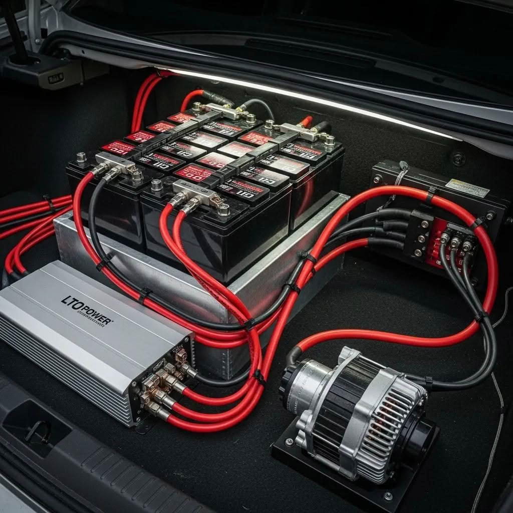
This guide explains the practical process for New Zealand and Australian car-audio systems: compatibility checks, alternator or charging-control choices, cable and fuse requirements, loaded-voltage testing, and commissioning. Install lithium banks securely in the rear cabin or boot, never under the bonnet.
Decide Whether Charging Above 15V Is Right for the System
A higher system voltage can reduce the current required for the same electrical input power. The relationship is current = power ÷ voltage. That can help a compatible amplifier maintain output, but it does not create free power or correct an undersized alternator, weak ground, restrictive fuse holder or unsuitable battery bank.
Before changing the regulator or alternator, record the vehicle’s present charging voltage at idle and at the intended demo RPM. Measure at the charging source and at the amplifier during a controlled bass load. If the source remains healthy while the amplifier voltage falls, the main problem is voltage drop through the cable, fuse, distribution or ground path. Follow the car-audio voltage-drop testing guide before buying another charging component.
Confirm the SCiB LTO Battery Limits First
Toshiba lists 2.4V nominal voltage for its 2.9Ah and 10Ah high-power SCiB cells and publishes their high-rate input and output characteristics. See Toshiba’s official high-power SCiB cell specifications for the manufacturer data.
A 6S bank has six cells in series. Its nominal voltage is 14.4V, while 2.8V per cell produces the 16.8V absolute maximum for six cells. Evolution Lithium’s approximately 15.6–15.9V normal high-performance range corresponds to roughly 2.60–2.65V per cell. The correct setting still depends on the exact bank, charging equipment and vehicle.
Use an active balancer suitable for the installed cell count and confirm individual cell voltages during commissioning. Pack voltage alone can hide an imbalanced cell. Stop testing if one cell approaches its limit, a terminal becomes hot, or the bank behaves differently from its supplied instructions.
Choose a Controlled Method to Raise Charging Voltage
High-output alternator with suitable regulation
A purpose-built high-output alternator with an appropriate regulator is the usual engine-running solution for a large demonstration or SPL system. Select it by usable output at the RPM where the system operates, not by its maximum headline rating. A 300A alternator that produces much less at idle may still leave a long demo in deficit.
Confirm the regulator can hold the intended set point without exceeding the limits of the battery, amplifiers or vehicle electronics. Avoid improvised voltage-raising modifications when their behaviour under heat, RPM and changing load has not been measured.
DC-to-DC charging for smart-alternator or isolated-bank applications
A compatible DC-to-DC charging strategy can provide controlled voltage to a rear bank when the factory system varies its output or when the raised-voltage audio bank must be isolated from sensitive OEM circuits. It must be rated for the chemistry, series count, input range and required charging current. A small DC-to-DC charger can maintain or recharge a bank, but it will not replace hundreds of amps of alternator support during sustained high-power playback.
External charging for maintenance and controlled top-up
An adjustable external charger or power supply can be useful for controlled maintenance when its output and current limit suit the exact bank. It is not a substitute for a correctly designed engine-running charging system. Monitor pack and cell voltages during the first charging sessions.
For the broader vehicle-conversion checklist, read how to upgrade a vehicle for an SCiB LTO battery above 15V.
Upgrade Cable, Grounds and Fuse Protection for the Current
Raising voltage does not remove the need for a low-resistance current path. Size cable from the maximum sustained current, total circuit length, installation temperature and acceptable voltage drop. Use secure crimped lugs, protected routing, clean metal-to-metal grounds and distribution hardware rated for the expected current.
Fuse every positive energy source close to its terminal. The fuse protects the conductor from fault current, so its rating must suit the cable and the available fault current. Blue Sea Systems’ DC circuit-protection and voltage-drop guidance explains why ampacity and voltage drop must both be considered when selecting conductors and protection.
After the wiring is complete, test the voltage at both ends of the current path under load. A good source reading with a low amplifier reading identifies loss in the installation. A falling source and amplifier reading points toward insufficient generation, depleted storage or an unsuitable charging strategy.
Commission the High-Voltage Car-Audio Charging System
- Fully inspect the bank, busbars, active balancer, cable, lugs, grounds, fuses and mounting.
- Confirm every connected component’s maximum operating voltage.
- Start with a conservative regulator or charger setting and measure at the source and rear bank.
- Check each cell before and during the first controlled charge.
- Run the vehicle at the RPM used for normal playback and record available alternator output.
- Apply a controlled audio load while monitoring source, bank and amplifier voltage.
- Check cable joints, fuse holders and terminals for abnormal heat.
- Increase the set point only within the approved bank and equipment limits.
- Repeat the loaded-voltage and temperature checks after the first full session.
| Test result | Likely issue | Next check |
|---|---|---|
| Source voltage is correct; amplifier voltage is low. | Voltage drop in cable, fuse, distribution or ground. | Measure across each connection under load. |
| Source and rear-bank voltage both fall during playback. | Charging output is below system demand, or storage is depleted. | Compare real alternator output with measured current demand. |
| Pack voltage looks normal; one cell is high or low. | Cell imbalance or a connection issue. | Stop and inspect cell voltages, busbars and the active balancer. |
| Voltage is stable; amplifier still clips or protects. | Gain, signal, impedance, thermal or amplifier limitation. | Diagnose the audio path rather than raising voltage again. |
If the source voltage is already unstable, use the step-by-step alternator and charging diagnosis for car audio before changing parts.
Conclusion: Raise Charging Voltage With Measurements, Not Guesswork
Increasing vehicle charging voltage above 15V can support a compatible SCiB LTO car-audio system, but the safe result comes from the complete electrical design. Confirm the battery and equipment limits, choose a regulated charging method, build a low-resistance fused current path, and verify source, bank and amplifier voltage under load.
For an applicable 6S SCiB bank, approximately 15.6–15.9V is the normal Evolution Lithium high-performance charging range and 16.8V is the absolute maximum. Treat those values as system limits and commissioning targets for the correct hardware, not a universal instruction for every vehicle.
Size the Battery Bank and Charging System Together
Use the Evolution Lithium car-audio battery calculator for amplifier RMS and alternator demand, browse the Evolution Lithium car-audio battery and electrical range, or send Evolution Lithium your amplifier RMS, final impedance, alternator rating and measured charging voltage for a configuration check.
High-Voltage Car-Audio Charging FAQs
Can a stock alternator charge a 6S SCiB bank at 15.6–15.9V?
Most factory charging systems are not designed to hold that range, and smart alternators may vary their output. Measure the vehicle first. Use only a charging method that can regulate the required voltage and is compatible with the vehicle and bank.
Is 16.8V a suitable daily charging target for a 6S SCiB bank?
No. It is the six-cell absolute maximum based on 2.8V per cell. For applicable Evolution Lithium 6S SCiB systems, normal high-performance charging is commonly approximately 15.6–15.9V. Follow the instructions for the exact bank.
Will higher voltage fix car-audio voltage drop?
Not when resistance in the cable, fuse, distribution or ground path is the cause. Compare voltage at the source and amplifier under the same load. Repair the current path before increasing the charging set point.
Do I need a bigger alternator or a bigger lithium bank?
A bigger alternator increases engine-running generation; a bigger bank increases stored energy and may increase current capability. Measure alternator output, amplifier demand, loaded voltage and required runtime to identify which limit the system is reaching.
Where should an SCiB LTO car-audio battery be installed?
Install it securely in the rear cabin or boot with protected cables, close-source fuse protection and an active balancer suited to the bank. Never install the lithium bank under the bonnet.