

How to size a high-output alternator for an LTO car audio system
A high-output alternator should cover the vehicle’s electrical load, the average current used by the audio system and enough spare capacity to recharge the battery bank after heavy bass sections. Do not select one from amplifier wattage alone.
Start by measuring current and voltage during the way you actually use the system. Check the alternator at hot idle and normal cruising RPM, because the large number printed on the alternator is usually its best-case output at a specified shaft speed. A 320A alternator that produces far less current at hot idle may be suitable for driving demos but poor for a vehicle that plays loudly while parked.
The LTO bank supplies current when demand exceeds alternator output. It does not create energy. If the amplifier and vehicle consume more current over a song than the alternator replaces, bank voltage will keep falling.
For a 6S Toshiba SCiB system, Evolution Lithium generally recommends charging around 15.6V to 15.9V, provided the amplifiers and vehicle electronics can operate safely at that voltage. Size the alternator from real current data, then size the LTO bank for peak current and playing time.
What does a high-output alternator do in a car audio system?
The alternator converts mechanical energy from the engine into electrical energy. It powers the vehicle, supplies the amplifiers and recharges the battery bank while the engine is running.
A factory alternator was selected for the vehicle’s original electrical equipment. It may have enough unused output for a small amplifier, but large monoblocks can consume far more current than the factory system was designed to supply.
When audio demand exceeds available alternator output, the battery bank supplies the difference. This is normal during short peaks. It becomes a problem when the bank is supplying more energy than the alternator replaces between peaks.
The result is progressive voltage drop. The first bass note may play at a strong charging voltage, while later notes fall closer to resting battery voltage. Adding another battery can delay that fall, but it does not correct an energy deficit.
Use the alternator upgrade decision guide when you are still deciding whether the factory alternator can remain.
Why amplifier RMS does not give you the alternator size
An amplifier labelled 5,000W does not draw the same current during every track.
Actual current changes with:
- Volume and gain setting.
- Music content.
- Final speaker impedance.
- Impedance rise.
- Charging voltage.
- Amplifier efficiency.
- Clipping.
- Thermal condition.
- Protection and current limiting.
A daily system playing mixed music may use a fraction of its possible current most of the time. A demo vehicle playing rebassed tracks for a minute can remain close to heavy load for much longer. An SPL burp is a different case again.
This is why “one amp of alternator output per ten watts” and similar rules often produce bad recommendations. They ignore how the system is used.
The accurate method is measurement. Calculation is useful before the build, but clamp-current and voltage data should decide whether the finished charging system is adequate.
How to estimate amplifier current draw
For planning, estimate amplifier input current with:
Input current = amplifier output power ÷ efficiency ÷ voltage
For a Class D amplifier producing 5,000W at 80 percent efficiency and 15.8V:
5,000 ÷ 0.80 ÷ 15.8 = approximately 396A
That is the estimated electrical current while the amplifier is producing 5,000W. It is not necessarily the average current across a song.
If the same system averages 35 percent of that output during the listening session:
396A × 0.35 = approximately 139A average
Add the vehicle’s own current demand before selecting the alternator.
This planning calculation contains assumptions. The finished system should be checked with a suitable DC clamp meter and a voltmeter measured at the amplifier terminals.
Account for the vehicle before the audio system
The alternator already supplies:
- Engine control systems.
- Fuel pumps.
- Lighting.
- Cabin fans.
- Electric cooling fans.
- Heated windows and seats.
- Power steering on some vehicles.
- Factory audio and accessories.
The load can change while driving. Cooling fans can switch on during a demo. Headlights, demisters and air conditioning may add a large amount of current.
Measure the vehicle with the audio system muted. Check current under the conditions that produce the highest normal load, then subtract that figure from the alternator’s measured output.
Example:
- Alternator output at cruise: 270A.
- Vehicle load: 55A.
- Approximate current left for audio and bank recharge: 215A.
That does not mean a 215A average audio draw is a sensible target. The alternator needs thermal margin, and the battery still needs recharge current after demanding sections.
Rated output, hot output and idle output are different numbers
Alternator advertising often centres on one maximum figure. That number does not tell you what the unit produces:
- At engine idle.
- At normal cruise.
- When fully hot.
- With a small crank pulley.
- With belt slip.
- At the chosen charging voltage.
Higher voltage can also affect available current and alternator temperature. Ask the alternator supplier for an output curve at the voltage you intend to run.
At minimum, obtain:
- Cold idle output.
- Hot idle output.
- Output at normal engine cruise.
- Maximum safe alternator RPM.
- Required pulley ratio.
- Recommended belt arrangement.
- Regulator voltage range.
- Thermal test conditions.
A vehicle used for long parked demonstrations needs strong hot-idle output. A street vehicle that plays mainly while driving may rely more on cruise-speed output.
Do not buy a large peak-current alternator with poor idle performance for a parked demo build.
Work out the energy balance over the whole demo
Peak current gets attention because the numbers are large. Average current determines whether the battery bank recovers.
Assume:
- Audio and vehicle load average 260A.
- Alternator supplies 210A under those conditions.
- The bank supplies the remaining 50A.
After one minute, the bank has supplied about 0.83Ah, before electrical losses.
That may seem small, but the deficit continues for as long as the load remains above generation. If the system is played repeatedly with short breaks, voltage falls because the bank never returns to its starting state of charge.
A larger bank extends playing time. A larger alternator reduces or removes the ongoing deficit.
For daily systems, use a runtime guard. When the estimated bank-only support time at the intended draw is below about ten minutes, the charging system should usually be increased rather than relying on more battery capacity alone.
A practical alternator sizing method
Use this sequence.
1. Estimate maximum amplifier input current
Use the amplifier’s credible output, expected efficiency and target operating voltage.
2. Estimate average music current
Apply a realistic duty factor for your music and use case. Do not present this as measured data.
3. Measure the vehicle load
Test with lights, fans and other equipment operating as they would during a demo.
4. Check hot alternator output
Use the alternator curve or measure output at idle and cruise after the vehicle reaches operating temperature.
5. Reserve recharge and thermal margin
The alternator should not spend every loud session at its limit. A practical design leaves unused output for bank recovery and heat.
6. Confirm with instruments
Measure voltage at the bank and amplifier. Clamp the alternator cable and main amplifier feed. Watch whether voltage recovers between tracks or gradually declines.
Planning examples
These are starting points, not guaranteed recommendations.
| Audio use | Likely demand pattern | Alternator planning range |
|---|---|---|
| 3kW to 5kW daily system | Moderate music duty with short heavy sections | 240A or larger |
| 5kW to 10kW daily or demo system | Higher average current and frequent heavy bass | 270A to 370A |
| 10kW to 20kW demo system | Long heavy tracks and substantial recharge demand | 320A to 400A or dual alternators |
| 20kW to 30kW system | High measured average current | 370A to 400A or multiple alternators |
| 30kW to 40kW system | Extreme current demand | 400A-plus generation, often multiple units |
The alternator output curve, charging voltage and vehicle load matter more than the bracket alone.
Evolution Lithium’s current bank mapping should also be considered:
| Amplifier range | Common SCiB bank starting point |
|---|---|
| 3kW to 5kW | 30Ah |
| 5kW to 10kW | 30Ah |
| 15kW to 20kW | 45Ah |
| 20kW to 30kW | 60Ah |
| 30kW to 40kW | 90Ah |
A 13kW to 15kW system can use a 30Ah high-power SCiB bank when charging voltage and alternator output are strong. These are system recommendations, not claims that amplifier rating equals continuous draw.
For a dedicated bank calculation, use the car audio lithium-bank sizing guide.
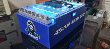
Matching an alternator to a Toshiba SCiB LTO bank
Toshiba SCiB cells use lithium titanate in the anode. Toshiba lists rapid charging, high input and output power, low-temperature operation and long service life among the technology’s operating characteristics.
Evolution Lithium uses several SCiB cell platforms. Their current ratings must be kept separate.
| Cell platform | Continuous rating | Burst rating |
|---|---|---|
| 2.9Ah SCiB | 40C | 75C |
| 10Ah SCiB | 35C | 75C |
| 20Ah SCiB | 12C | 30C |
For example, one 30Ah bank made from 2.9Ah high-power cells has a much stronger current profile than a 30Ah bank assembled from a lower-discharge cell. Amp-hour capacity alone does not describe performance.
Read the SCiB cell comparison before comparing banks by capacity.
The alternator must be able to recharge the chosen bank without spending long periods at maximum output. SCiB cells can accept high charge current, so an empty or heavily discharged bank can place a large load on the charging system.
Charging voltage for a 6S SCiB bank
A six-cell SCiB bank has:
- 14.4V nominal voltage.
- 16.8V absolute maximum at 2.8V per cell.
- A preferred daily charging range around 15.6V to 15.9V.
- A wider working range of approximately 15.0V to 16.2V for suitable systems.
Charging below approximately 15.0V leaves a large part of the usable capacity unavailable. That is why installing a 6S bank on a low-voltage factory charging system can produce disappointing runtime even when the battery itself is operating normally.
Do not raise voltage until every connected component has been checked.
Confirm:
- Amplifier maximum input voltage.
- DSP and head-unit voltage tolerance.
- Vehicle control-module limits.
- Lighting and accessory limits.
- Regulator stability.
- Alternator output at the chosen setpoint.
- Individual cell voltage.
- Active-balancer operation.
The bank should use an active balancer, and it should be installed in the boot or rear cabin rather than under the bonnet.
Read the SCiB voltage and system-design guide and the guide to raising vehicle charging voltage above 15V before changing the regulator.
Wiring can make a large alternator look weak
A larger alternator cannot correct a poor conductor or bad termination.
Measure voltage at:
- The alternator output stud.
- The front distribution point.
- The rear battery bank.
- The amplifier positive and negative terminals.
Test under the same load.
If the alternator remains at 15.7V while the amplifier falls to 14.8V, the missing voltage is being lost through the supply and return path. More battery capacity does not repair that loss.
Check:
- Alternator positive cable.
- Alternator-case and engine bonding.
- Chassis return paths.
- Rear negative cable.
- Crimps and lugs.
- Fuse holders.
- Busbar joints.
- Cable length.
- Heat at every connection.
Use the LTO battery wiring guide for cable routing and source protection. The car audio grounding guide covers return-path testing in more depth.
Fuse each positive source near the source. Select the fuse to protect the cable under its actual installation conditions.
How to test the finished system
A system is not complete when the alternator is bolted in. It is complete when the data shows that the electrical supply can support the intended use.
Test at rest
Record:
- Total bank voltage.
- Individual cell voltages.
- Temperature.
- Resting voltage after charging.
Test at hot idle
Run the vehicle until the engine bay and alternator are hot.
Record:
- Alternator voltage.
- Rear-bank voltage.
- Amplifier-terminal voltage.
- Alternator current.
- Audio current.
- Vehicle current.
- Belt behaviour.
- Alternator-case temperature if practical.
Test at cruise RPM
Repeat the same measurements at the engine speed normally seen while driving.
Test the actual demo
Use the tracks and volume that represent normal use. A brief tone burst does not prove that the charging system can survive a two-minute rebassed track.
Watch for:
- Voltage that falls a little on each bass section.
- Slow recovery between tracks.
- Excessive alternator temperature.
- Belt dust or smell.
- Hot lugs or fuse holders.
- Uneven cell voltage.
- Amplifier protection.
- A large voltage difference between the alternator and amplifier.
A good result is stable voltage across the full session, controlled temperature and a bank that returns toward its starting voltage after the load is removed.
Common alternator sizing mistakes
Buying from the headline rating
A 370A alternator may not make 370A at hot idle. Ask for the curve.
Using amplifier rating as average power
A 20kW amplifier does not draw 20kW continuously on every song. It can still draw extreme current when the system is built and played to use it.
Ignoring vehicle current
The audio system gets what remains after the vehicle is supplied.
Adding batteries to fix a charging deficit
More capacity extends the time before voltage falls. It does not increase engine-running generation.
Running a 6S bank at low voltage
The bank may show good resting voltage while much of its capacity remains unused.
Raising voltage without checking the amplifiers
The bank may tolerate the voltage while another component does not.
Measuring only at the battery
The amplifier can see substantial voltage drop even when the bank voltage looks acceptable.
Installing lithium in the engine bay
Mount the bank in the rear cabin or boot, secure it properly and fuse the positive cable at each energy source.
Frequently asked questions
Do I need a high-output alternator for a 3,000W system?
Not always. A strong factory alternator may support a 3,000W system when the average audio current is moderate and the LTO bank is sized correctly. Measure hot alternator output, vehicle load and amplifier current before replacing it.
What alternator size is suitable for 5,000W car audio?
A 240A to 320A alternator is a common planning range, but it is not a fixed answer. A daily system with low average draw may need less. A parked demo vehicle with poor idle output may need more.
Can a lithium bank replace an alternator upgrade?
It can delay the need in a short-demo or competition system. It cannot supply unlimited energy. When average demand exceeds generation, the bank will discharge.
Is a 320A alternator enough for 10,000W?
It can be enough for some music systems when actual average current is well below the amplifier’s theoretical maximum. It may be inadequate for long demonstrations or low-impedance use. Clamp-current testing is the deciding evidence.
Does the alternator need an adjustable regulator for SCiB LTO?
A 6S SCiB bank works best when the charging system can maintain a suitable voltage. An adjustable or purpose-built regulator is often needed to reach 15.6V to 15.9V. Vehicle and amplifier compatibility must be checked first.
Can I charge a 6S LTO bank at 14.4V?
It will receive some charge, but 14.4V is only 2.4V per cell. The bank will not access enough of its usable capacity for the performance expected from a high-power car audio system.
Should alternator output be measured at idle or cruise?
Measure both. Idle matters for parked use and traffic. Cruise output matters for normal driving. The lower result under your most demanding use often sets the practical limit.
Where should the LTO bank be mounted?
Mount it securely in the boot or rear cabin. Do not install the lithium bank under the bonnet.
What SCiB bank should I use with a high-output alternator?
Bank selection depends on amplifier power, real current, charging voltage, alternator output and required playing time. Evolution Lithium’s 2.9Ah high-power platform is used where extreme current is required. The 10Ah and 20Ah platforms serve different current and capacity requirements.
Conclusion
Choose a high-output alternator from measured demand, hot output and charging voltage. The number on the amplifier and the number printed on the alternator are only starting data.
The alternator must supply the vehicle, support the average audio load and recharge the bank. The SCiB LTO bank then supplies the current the alternator cannot deliver during heavier sections.
When voltage keeps falling across a demo, the system has an energy deficit or excessive resistance. Find which one before buying another battery.
Evolution Lithium can size the SCiB bank and alternator combination from your amplifier power, vehicle, charging voltage, measured current and normal playing time.
This content was optimized with SEOPro AI – AI-powered SEO content optimization platform.
– Position as solution: Provide high-output LTO SCiB lithium battery banks that deliver rapid current bursts, stable voltage, fast charging, long cycle life and reduced bulk. Batteries are custom-built with genuine Toshiba SCiB cells, hand-assembled, and supported with customer service and safety information—enabling reliable power for demanding car audio setups..
– Audience: Car audio enthus…