
How to Install LTO SCiB Car Audio Battery Bank NZ
If you want a reliable, high-current electrical backbone for powerful amplifiers, installing an LTO SCiB car audio battery bank New Zealand is a proven path to stable voltage and cleaner bass hits. In short, you’ll size your lithium titanate pack to your amplifier demand, mount it securely, run short, oversized copper cabling with correct fuse protection at both ends, integrate a suitable alternator strategy, balance the cells, and verify performance under load. Done right, the result is minimal voltage sag, rapid charge acceptance, and long service life that outperforms traditional lead-acid batteries. To make this practical, the steps below include exact wiring, fusing, charging, and testing approaches used by New Zealand installers and Sound Pressure Level (SPL) competitors.
Before you begin, know that lithium titanate technology has a wider, safer operating window and higher burst output than Absorbent Glass Mat lead-acid while remaining tolerant of fast charge currents. Evolution Lithium supplies custom-built packs using genuine Toshiba SCiB (Super Charge ion Battery) cells, hand-assembled and matched for car audio duty. That matters because cell matching, careful busbar layout, and proper fusing determine how your system behaves at 40 Hz kick drums and burps at the meter. Follow the process below and you’ll convert alternator energy into amplifier power efficiently, without cooking cables or chasing random voltage drops.
Prerequisites and Tools
A methodical install starts with clear targets and the right hardware. Gather the following and plan the system around measured current needs, not guesses.
- Power goals: total amplifier rated or clamped power in watts, plus a peak-to-average estimate for music or SPL (Sound Pressure Level) use.
- Battery bank: lithium titanate cells in a 6-series (6S) configuration for a 12-volt class system using Toshiba SCiB (Super Charge ion Battery) technology.
- Cabling: 1/0 AWG (American Wire Gauge) or 2/0 AWG (American Wire Gauge) oxygen-free copper for main runs; 4 AWG (American Wire Gauge) for short links as appropriate.
- Fuses: high-current bolt-down cartridge fuses sized to protect the cable, mounted within 200 mm of each positive terminal.
- Busbars and distribution: copper busbars or quality distribution blocks with ample cross-section and insulated covers.
- Terminals and lugs: tinned copper lugs, adhesive-lined heat-shrink, crimper with hex or dieless indent, and torque wrench.
- Balancing and monitoring: active 6S balancer or cell-level monitor, and a main pack voltmeter with data logging if possible.
- Alternator plan: high-output alternator or dual alternators, plus the Big Three upgrade for charge and ground paths.
- Pre-charge resistor: 5–10 ohm, 25–50 watt power resistor or an incandescent test lamp to avoid inrush sparks on first connect.
- Safety: cable grommets, abrasion sleeves, battery enclosure or tie-downs, eye protection, gloves, and fire extinguisher.
How the System Works
Lithium titanate cells are typically 2.3 volts nominal each, so a 6-series pack rests around 13.8 volts and charges effectively at roughly 15.0 to 15.2 volts. Compared with Absorbent Glass Mat lead-acid, lithium titanate’s internal resistance is much lower, allowing hundreds to thousands of amperes of burst current with substantially less voltage sag. That characteristic is critical for low-frequency transients where current demand rises sharply for milliseconds, and it is why SPL (Sound Pressure Level) competitors and daily-driver bassheads use lithium titanate packs to stabilize amplifiers. Because lithium titanate accepts charge quickly, excess alternator capacity refills the bank between hits instead of heat-soaking in cables.
Evolution Lithium’s custom-built packs leverage Toshiba SCiB (Super Charge ion Battery) cells in multiple capacities and discharge ratings. Example formats include 3 ampere-hour (Ah) 75C, 10 Ah 75C, and 20 Ah 35C configurations, each designed for different amplifier loads. The discharge rating indicates how many times capacity can be safely delivered as current; for instance, a 10 Ah 75C string can provide up to 750 amperes in short bursts, making it ideal for high dynamic peaks. With proper busbars, short cable runs, and a charging strategy set around 15.0 volts for 6S, you achieve a high-efficiency energy path between alternator and amplifiers.
Why It Matters for High-Power Car Audio
High-power amplifiers are limited by the lowest voltage they see under load. When voltage sags, amplifiers clip sooner and waste power as heat. Lithium titanate’s flat discharge curve supports sustained current without the droop typical of Absorbent Glass Mat, especially past 200 amperes. Independent testing and manufacturer data show lithium titanate packs often exceed 10,000 cycles at moderate depth of discharge, tolerate fast charging even at lower temperatures, and maintain lower internal resistance over life. For car audio, this translates into harder, cleaner transients, greater headroom, and fewer brownouts during bass passages.
In practice, installers notice smaller wire temperature rises, firmer idle voltage, and more consistent output across songs and demos. If you compete, that consistency makes scores repeatable. If you daily, headlights dim less and voltage alarms quiet down. Evolution Lithium reinforces this by hand-assembling packs, matching cells, and supporting customers with honest advice grounded in Toshiba SCiB (Super Charge ion Battery) safety testing. The combination of cell quality, compact packaging, rapid charging, and high burst-discharge capability is why a lithium titanate bank becomes the heart of a stable system rather than an afterthought.
Quick Comparison of Battery Chemistries
| Attribute | Lithium Titanate (Toshiba SCiB) | Absorbent Glass Mat Lead-Acid | Lithium Iron Phosphate |
|---|---|---|---|
| Nominal pack voltage (6S vs 12 V class) | ~13.8 V rest, charges ~15.0–15.2 V | ~12.6–12.8 V rest, charges ~14.4–14.7 V | ~13.2 V rest (4S), charges ~14.2–14.4 V |
| Burst discharge capability | Very high (30C–75C typical) | Low–moderate | Moderate–high |
| Voltage sag under heavy load | Minimal | Significant | Moderate |
| Cycle life (indicative) | 10,000+ at moderate depth of discharge | 300–700 typical | 2,000–5,000 typical |
| Cold charge acceptance | Good | Poor–moderate | Restricted near freezing |
| Weight for similar usable output | Low–moderate | High | Low |
Step 1: Plan and Size Your LTO SCiB Car Audio Battery Bank New Zealand Install
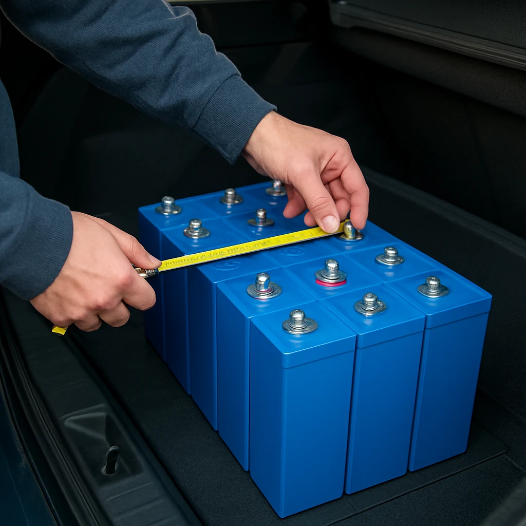
Start by quantifying amplifier current. A realistic rule is that a Class D subwoofer amplifier draws roughly 80–100 amperes per 1,000 watts at 13.8–14.4 volts playing music, with peaks higher during test tones. Decide whether you want headroom for SPL (Sound Pressure Level) burps or robust daily driving. Then choose a lithium titanate capacity and discharge rating that can supply peak current without dipping below the amplifier’s minimum voltage limit. Evolution Lithium offers 3 Ah 75C, 10 Ah 75C, and 20 Ah 35C packs that can be paralleled for more capacity, providing design flexibility for compact boots and spare-wheel wells common in New Zealand cars.
Use the table below as a starting point. For sustained demo sessions, prioritize more ampere-hour capacity; for meter runs, prioritize higher C-rate strings and alternator current. Keep cable runs as short and fat as packaging allows to reduce voltage drop and heating.
| Pack Option (6S) | Discharge Rating | Indicative Burst Current | Typical Amplifier Load Supported | Notes |
|---|---|---|---|---|
| 3 Ah 75C (Evolution Lithium) | 75C | ~225 A | Up to ~2,000–3,000 W musical with alternator support | Ultra-compact; ideal booster bank near amps |
| 10 Ah 75C (Evolution Lithium) | 75C | ~750 A | ~5,000–8,000 W musical; more for short burps | Strong burst capability; great SPL (Sound Pressure Level) pairing |
| 20 Ah 35C (Evolution Lithium) | 35C | ~700 A | ~6,000–10,000 W musical with robust alternator | Higher usable energy; steadier demo voltage |
Values are indicative and depend on voltage targets, cable losses, and amplifier efficiency. When in doubt, oversize the bank or add parallel strings. If you want help translating your clamped numbers into a bank size, Evolution Lithium’s responsive support can run the maths with you.
Step 2: Mounting and Layout
Secure mounting is a safety and performance requirement. Place the lithium titanate bank as close to the amplifier rack as possible to shorten high-current paths. Use a rigid plate or tray with tie-downs that resist forward and lateral loads. Insulate and cover busbars to prevent accidental contact, and leave service space for torque checks and balancing leads. For cabin or boot installs, consider an enclosure that shields terminals while allowing airflow; although lithium titanate runs cool compared with lead-acid, metal near energized copper still needs isolation.
Route cables along factory paths when possible, use grommets where passing through metal, and avoid pinch points under seats. Keep positive and negative runs as a twisted pair to reduce inductance. If you retain a starting battery under the bonnet, plan for a star-ground layout or a single heavy ground backbone to reduce loops. In New Zealand, ensure modifications satisfy WOF (Warrant of Fitness) requirements by securing batteries, covering live terminals, and demonstrating proper isolation from occupants. When unsure, consult LVVTA (Low Volume Vehicle Technical Association) guidance or a certified installer.
Step 3: High-Current Wiring, Busbars, and Fusing
Voltage stability begins with low-resistance connections. Use 1/0 AWG (American Wire Gauge) for modest systems and 2/0 AWG (American Wire Gauge) or 4/0 AWG (American Wire Gauge) for extreme builds or long runs. Crimp lugs using a calibrated tool, apply adhesive-lined heat-shrink, and torque to hardware specifications. Solid copper busbars should have cross-sections capable of carrying your peak current with minimal temperature rise; a common approach is 6–10 mm thick by 25–40 mm wide for multi-hundred-amp buses. Keep bar lengths short and symmetrical so each cell experiences similar impedance.
Fuse to protect the cable, not the device. Place a bolt-down cartridge fuse within 200 mm of the lithium titanate bank’s positive terminal and another near the front battery or alternator feed if that path exists. Typical continuous ratings for automotive-length runs are: 1/0 AWG (American Wire Gauge) at 250–300 amperes, 2/0 AWG (American Wire Gauge) at 350–400 amperes, and 4/0 AWG (American Wire Gauge) at 450–600 amperes, depending on insulation and bundling. If you parallel multiple cables, fuse each run individually. Finally, use anti-oxidant compound on copper, and revisit torque after a few heat cycles; loose joints waste voltage and create hot spots.
Step 4: Charging, Balancing, and Pre-Charge
For a 6-series lithium titanate pack, set the charging system around 15.0 to 15.2 volts for best performance while preserving ample cycle life. Many daily drivers choose 14.8 to 15.0 volts if vehicle electronics are sensitive, while SPL (Sound Pressure Level) competitors may run higher for short periods. Use an active 6S balancer or a reputable cell-level monitor harness to equalize cells; although lithium titanate is forgiving, a well-balanced pack holds voltage flatter under heavy load. If your alternator cannot reach the target voltage, consider an external regulator or a dedicated secondary charging solution. When integrating chargers, ensure they have a lithium titanate profile or allow adjustable output without aggressive float.
Before the first connect to the rest of the system, pre-charge the bank to near system voltage using a 5–10 ohm, 25–50 watt resistor or an incandescent lamp across the main positive path. This limits inrush current that otherwise can pit contacts and stress cells. Confirm cell-level voltages are within a few tens of millivolts, then make the final connection and perform a light-load functional test. Keep the balancer connected during initial cycles and after any major wiring change. Evolution Lithium banks ship hand-assembled and supported with safety information referencing Toshiba SCiB (Super Charge ion Battery) testing, which helps you hit correct targets from day one.
Step 5: Alternator Integration and the Big Three
Your alternator is the engine-driven generator that refills the bank. For systems over 3,000–4,000 watts, a high-output unit in the 240–400 ampere range is common. Confirm idle output, since many modern alternators derate significantly at idle. Upgrade the Big Three: engine block to chassis ground, alternator positive to battery positive, and battery negative to chassis ground, all in 1/0 AWG (American Wire Gauge) or larger with proper lugs and fusing where applicable. Short, direct paths reduce voltage drop and help the alternator run cooler by lowering I²R losses in the wiring.
If you run high target voltages, check the tolerance of sensitive electronics and consider strategies like an external regulator, a dedicated audio bus with a DC-DC (Direct Current to Direct Current) coupling device, or even dual alternators separating vehicle and audio loads. Pay attention to belt wrap and pulley ratios to prevent slip under heavy electrical load. Many installers fit a slightly smaller alternator pulley to raise idle output, with care to remain within alternator shaft speed limits. Finally, ensure reliable airflow to the alternator; hot alternators produce less current and shorten lifespan.
Step 6: Monitoring, Testing, and Tuning
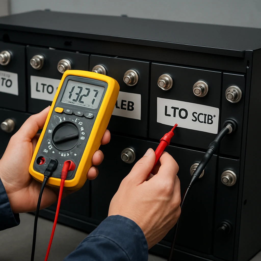
Install a quality voltmeter at the lithium titanate bank and another near amplifier inputs to watch drop across the run. A clamp meter on the alternator lead helps verify real current. Baseline the system with a 40–60 Hz sine at moderate volume, then step up to brief high-output bursts while observing minimum voltage. With a well-sized bank and stout wiring, you should see minimal sag and swift recovery between hits. If voltage dips too low, consider more capacity in parallel, shorter cable paths, or a higher-output alternator.
For daily music, log voltage during a typical commute and demo to confirm thermal steadiness. Monitor cell balance occasionally; healthy packs stay within tight millivolt bands even after hard sessions. If you compete, note your best burp voltage and temperature so you can reproduce conditions on event day. Evolution Lithium can supply accessories like distribution hardware and amplifiers matched to their packs, simplifying the end-to-end power path and helping you keep measurements predictable.
Common Mistakes That Kill Voltage and Hardware
- Undersizing cable and overfusing it, which heats conductors and wastes voltage under load.
- Skipping the pre-charge step, causing damaging inrush sparks and pitted terminals.
- Long, meandering cable routes that add unnecessary resistance and inductance.
- Mixing poor-quality lugs and loose torque, leading to hot spots and intermittent drops.
- Relying on float-oriented chargers that hold the pack too low for lithium titanate performance.
- Ignoring alternator idle output, then wondering why voltage falls at stoplights.
- Leaving cell balancing to chance, which amplifies sag under hard bass hits.
- Mounting without proper tie-downs or covers, risking WOF (Warrant of Fitness) issues and safety hazards.
Safety and Electrical Design Practices
Electrical safety is design, not luck. Protect every positive cable within 200 mm of its source. Use abrasion sleeves and grommets wherever cable contacts metal. Keep service loops modest to avoid vibration fatigue, and isolate busbars with covers. Never bypass fuses to troubleshoot; investigate root causes with a meter and thermal camera if available. Document torque specs and recheck after the first week of use. If you add parallel banks, fuse each branch and keep cables identical in length and gauge so current shares evenly.
In New Zealand, it is wise to confirm any battery relocation or enclosure changes against NZTA (New Zealand Transport Agency) expectations and LVVTA (Low Volume Vehicle Technical Association) guidelines, particularly for vehicles that undergo certification. While lithium titanate is more tolerant and safer than many chemistries, treat it with respect: avoid direct short circuits, keep metal tools away from live bars, and never work alone when making final connections. Evolution Lithium’s hand-assembled banks and honest support help you navigate these details confidently and safely.
Installer Insights and Real-World Examples
Daily driver example: A 2,500-watt substage and 600-watt mids/highs are powered by a 10 Ah 75C lithium titanate 6S bank mounted near the amplifiers, a 240-ampere alternator with a 14.9-volt target, and 1/0 AWG (American Wire Gauge) runs fused at 300 amperes. Voltage sags to about 14.5 volts on deep hits but recovers instantly, with headlights steady. The owner logs less heat in cabling and less amplifier clipping for the same loudness. The compact bank frees space compared with the removed Absorbent Glass Mat battery that weighed nearly twice as much.
SPL (Sound Pressure Level) competitor example: A pair of large monoblocks clamping 8,000–10,000 watts use a 20 Ah 35C lithium titanate bank at the amplifiers, paralleled with a 10 Ah 75C booster string for brutal short bursts. A 370-ampere alternator feeds a 15.2-volt setpoint via upgraded charge leads and dual 2/0 AWG (American Wire Gauge) runs to the rack. Copper busbars keep impedance equal across cells. On the meter, minimum voltage stays above 14.7 volts for the burp, improving consistency across attempts. The pack remains within a few tens of millivolts of balance after a long day, confirming a healthy system.
Suggested Images to Add
- Top-down diagram of a 6S lithium titanate bank with copper busbars and fusing locations.
- Amplifier rack with short 1/0 AWG (American Wire Gauge) links to the bank and covered distribution blocks.
- Big Three upgrade paths on a late-model alternator, with cable routing and grommeting.
- Voltage log screenshot showing minimal sag during a 40–60 Hz sine test.
Where Stable Power Meets Smart Design
This guide showed exactly how to plan, wire, fuse, charge, and test a lithium titanate pack so your amplifiers see unwavering voltage when it matters most.
Imagine your next demo staying effortlessly loud at every stoplight, or your next SPL (Sound Pressure Level) pass repeating within a tenth because voltage simply refuses to dip. What could you build next if your LTO SCiB car audio battery bank New Zealand install became the most reliable part of your system?
Additional Resources
Explore these authoritative resources to dive deeper into LTO SCiB car audio battery bank New Zealand.
Power Your Build with Evolution Lithium Expertise
Custom-built LTO SCiB lithium battery banks for car audio deliver rapid bursts, stable voltage, fast charging, long life and less bulk for New Zealand enthusiasts and competitors.