No products in the cart.
No products in the cart.

No products in the cart.
No products in the cart.
If your headlights dim when the bass hits, your car’s electrical system may be struggling to maintain a stable voltage when the amplifier demands a sudden burst of current.
The cause could be an undersized alternator, excessive resistance in the power or ground wiring, a weak battery, or simply more electrical demand than the system was designed to support.
A brief change in brightness doesn’t automatically mean you need a new alternator or another battery. But noticeable dimming, amplifier shutdowns or repeated low-voltage warnings deserve investigation.
The best fix is to measure voltage at the source and amplifier under load, identify where the electrical system is struggling, and correct that specific problem.
This guide explains how to check your system, interpret the results and decide whether a wiring upgrade, alternator upgrade or properly matched lithium battery bank makes sense.
Bass-heavy music creates sudden changes in amplifier current demand.
When your subwoofer plays a demanding bass note, the amplifier draws electrical power from the vehicle’s charging system and battery. If the supply cannot maintain voltage under that load, voltage may temporarily fall.
Depending on the vehicle’s lighting technology and electrical controls, that change can become visible as headlights dimming or flickering in time with the bass.
The relationship is straightforward:
Power (W) = Voltage (V) × Current (A)
For example, supplying 3,000 W of electrical input power at 14 V requires approximately 214 A.
That’s electrical input power, not amplifier RMS output. An amplifier producing 3,000 W RMS will draw more than 3,000 W from its electrical supply because it isn’t 100% efficient.
Current demand also changes with music, volume, impedance and amplifier operation.
This is why a system that behaves normally at low volume can develop noticeable voltage sag during heavier bass passages.
There are two main electrical problems to investigate:
Both problems can occur together.
Not every brief brightness change means an electrical component is failing.
However, the behaviour of the lights provides useful diagnostic clues.
| What You Notice | What It May Indicate |
|---|---|
| Brief dimming on individual bass hits | Transient electrical demand or momentary supply-voltage sag |
| Dimming mainly at idle | Limited alternator output at lower engine speed |
| Dimming during sustained bass | Sustained current demand exceeding available charging support |
| Dimming with amplifier protection or shutdown | Voltage at the amplifier may be falling below its operating requirements |
| One headlight flickering independently | A local lighting connection, driver or control fault rather than the audio system alone |
| Dashboard warnings or other electrical faults | A broader charging or vehicle electrical problem requiring investigation |
These are diagnostic clues, not confirmed causes.
Safety: If the headlights become dangerously dim, warning lights appear, wiring becomes hot or you notice burning smells, stop using the high-power audio system until the fault has been investigated.
Your alternator supplies much of the electrical power while the engine is running.
However, its rated maximum output isn’t necessarily what it produces at idle.
A 250 A alternator, for example, should not automatically be treated as a 250 A supply under every operating condition.
Actual output depends on alternator speed, temperature, regulator behaviour and the vehicle’s electrical demands.
If the amplifier requires more current than the alternator can provide, the battery supplies the difference. During repeated or sustained high loads, battery voltage can fall.
For a detailed assessment, see our high-output alternator upgrade guide for car audio.
A high-current amplifier needs a low-resistance electrical path.
Loose terminals, corroded connections, poorly crimped cable lugs, unsuitable fuse holders and weak ground connections can all introduce unwanted resistance.
That resistance produces voltage loss whenever current flows.
For example, a connection with just 0.005 ohms of resistance would produce a 0.5 V drop at 100 A. At that current, the connection would also dissipate 50 W as heat.
A small resistance can become a significant problem in a high-current installation.
If your wiring is suspect, start with our car audio grounding guide before buying additional equipment.
Cable resistance increases with cable length and decreases as conductor cross-sectional area increases.
This matters particularly when the battery bank is installed in the boot or rear cabin and the amplifier draws substantial current.
Cable selection should account for:
Simply installing a larger battery will not repair an undersized or poorly terminated power cable.
A battery that is discharged, deteriorated or unsuitable for the current demand may allow greater voltage sag during heavy bass passages.
A healthy battery bank with suitable current-delivery capability can help support short, demanding amplifier loads.
However, a battery stores energy. It does not create additional alternator output.
If your charging system cannot replenish the energy being used, sustained playback will eventually deplete the available reserve.
Modern vehicles may use variable-voltage alternator regulation, battery monitoring systems and electronically controlled lighting.
Some LED and HID systems also respond differently to supply-voltage changes than conventional halogen headlights.
This means headlight dimming should not be diagnosed from battery voltage alone.
If the lights flicker without any corresponding audio-related voltage change, investigate the lighting circuit, driver electronics and vehicle charging controls.
Before spending money on upgrades, collect measurements that help isolate the problem.
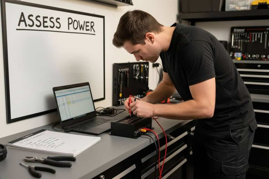
A digital multimeter with suitable DC voltage measurement capability is useful. A meter with a fast minimum/maximum capture function or a properly connected automotive oscilloscope can provide additional information about brief transients.
Park on level ground in a safe, well-ventilated location.
Apply the parking brake, secure the vehicle and ensure any leads cannot contact moving engine components, hot surfaces or exposed high-current terminals.
Use insulated, correctly rated test leads. Secure probes before testing wherever practical.
Never connect a multimeter set to current-measurement mode directly across a battery or battery bank.
Do not disconnect the battery while the engine is running.
If you are unfamiliar with testing live high-current circuits, have a qualified automotive electrical technician perform the measurements.
With the engine running at normal idle and the audio system at a low volume, measure voltage directly across the terminals of the battery or bank that supplies your audio system.
Record:
Keep electrical accessories and engine conditions consistent for subsequent tests.
Play a familiar bass-heavy passage at a controlled volume.
Increase the volume only as necessary to reproduce the symptom. Do not exceed the amplifier, speakers or electrical system’s safe operating limits.
Record the lowest reliably captured voltage at the source terminals.
Repeat the passage under the same conditions to check whether the result is consistent.
A normal digital multimeter may not capture the lowest voltage during a very short bass transient. Treat the recorded minimum as an observation, not necessarily the true instantaneous minimum.
Measure DC voltage directly across the amplifier’s positive and negative power-input terminals.
Use the same music passage and comparable operating conditions.
Compare the amplifier voltage with the source voltage.
If source voltage remains relatively stable but amplifier voltage drops substantially, investigate the power and ground connections between them.
If both voltages fall together, investigate charging capacity, battery condition and source-bus behaviour.
For an accurate direct comparison during rapidly changing loads, measure the two locations simultaneously using suitable equipment. Sequential multimeter readings can be misleading when the load changes between tests.
To locate wiring losses, a technician can perform loaded voltage-drop tests across the relevant sections of the positive supply and negative return circuits.
These tests measure voltage across a cable or connection while current is flowing—not simply the overall voltage between positive and negative terminals.
A significant loss across one connection, cable or fuse holder identifies a restriction worth investigating.
Fluke explains the principles in its automotive voltage-drop troubleshooting guide.
| Measurement | Result |
|---|---|
| Source voltage at idle | _____ V |
| Source voltage during bass | _____ V |
| Amplifier voltage during bass | _____ V |
| Positive supply-path voltage loss | _____ V |
| Negative return-path voltage loss | _____ V |
| Engine speed during test | _____ RPM |
| Headlight behaviour | _____ |
Record whether readings were simultaneous and how the minimum voltage was captured.
Repeat the test after any corrective work so you can confirm whether it actually improved performance.
Use your measurements to identify the next test or repair.
| Measurement Pattern | Likely Investigation | Recommended Action |
|---|---|---|
| Source and amplifier voltage both sag | Charging supply or battery reserve | Test alternator output and battery condition |
| Source stable, amplifier voltage low | Cable or connection resistance | Test positive and negative paths under load |
| Voltage improves markedly with engine RPM | Alternator output at idle | Assess charging output across operating speeds |
| Voltage decreases progressively during extended playback | Sustained energy deficit | Compare average demand with charging supply |
| Source and amplifier voltage stable, headlights still flicker | Lighting-system or local wiring fault | Test headlight supply, grounds and controls |
Important: There is no single voltage reading that proves every car-audio system is safe or adequately supported.
Acceptable operating voltage depends on battery chemistry, amplifier specifications, the vehicle’s charging strategy and the measurement location.
A better diagnosis identifies both where voltage falls and why.
Once you know which part of the system is responsible, choose the appropriate fix.
Inspect the condition and security of terminals, fuse holders, lugs, positive cables and grounding points.
Damaged, corroded or incorrectly installed components should be repaired or replaced using appropriate electrical hardware.
Work on de-energised circuits and follow the correct isolation procedure for the vehicle and battery chemistry.
Larger, correctly installed OFC cables can reduce resistive losses when the existing wiring is undersized.
A Big 3 upgrade can improve the vehicle’s major charging and grounding paths where those paths are restricting current.
It does not increase the alternator’s generating capacity.
For additional background, see Crutchfield’s explanation of Big 3 wiring and alternator upgrades.
If the charging system cannot support the amplifier and vehicle’s combined demand, a properly sized high-output alternator may be necessary.
Pay attention to output at idle, not simply the advertised maximum amperage.
A larger alternator may also require correctly rated wiring, protection and installation hardware.
A capacitor can supply or absorb energy over brief intervals, but its usefulness depends on the load, capacitance, circuit resistance and charging system.
It cannot make up for a persistent shortage of electrical energy during sustained high-power playback.
For large amplifier systems with a continuing current deficit, correcting alternator, battery or wiring limitations is usually more important than adding a capacitor.
Read our capacitor versus battery comparison for car audio systems for a more detailed explanation.
Battery capacity, continuous discharge capability, amplifier demand and alternator output must be considered together.
Use the Evolution Lithium Battery & Alternator Calculator to estimate current demand and compare suitable battery-bank configurations for your amplifier.
The calculator is a planning tool. Confirm the design against measured operating conditions and actual equipment specifications before installation.
Calculate Your Battery & Alternator RequirementsA correctly specified lithium battery bank can help maintain electrical supply during demanding bass passages, particularly where the existing battery cannot deliver the required current without excessive sag.
But lithium is not a universal solution.
If the fault is a poor ground connection, undersized cable or damaged fuse holder, installing a more capable bank will not eliminate that restriction.
Likewise, additional stored energy will not solve a continuous alternator shortage indefinitely.
The correct bank depends on the vehicle’s charging voltage, amplifier requirements, available alternator support, desired runtime and system configuration.
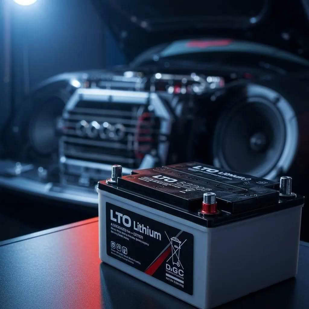
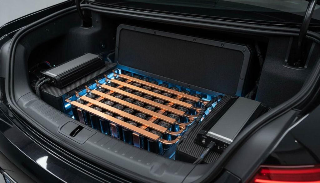
Toshiba SCiB lithium titanate cells are well suited to applications where high current delivery and voltage performance under demanding loads matter.
Evolution Lithium’s 3Ah-cell SCiB LTO banks prioritise high-current discharge for demanding amplifier systems.
They are designed for appropriately configured electrical systems, not as direct replacements for every standard 12 V battery.
For 6S SCiB installations, Evolution Lithium commonly targets approximately 15.6–15.9 V charging, subject to the exact cell model and the voltage ratings of all connected equipment.
Building a high-power car audio or SPL system? Explore Evolution Lithium’s 3Ah-cell SCiB LTO banks, available in configurations from 15Ah to 90Ah.
Suitable for compatible electrical systems requiring high current delivery and carefully managed charging voltage.
View Toshiba SCiB LTO Battery BanksFor applications with charging voltage appropriately limited to 14.6 V or below, an EVE LiFePO4 bank may be a better match.
Evolution Lithium’s 22Ah-cell EVE range includes finished banks for different electrical demands and available installation space.
The system must still have suitable charging support, correctly designed wiring, appropriate protection and an active balancer.
Explore Evolution Lithium’s EVE 22Ah-cell LiFePO4 banks for compatible car-audio electrical systems.
Compare available capacities and choose a configuration based on your amplifier’s actual electrical demand.
Explore EVE LiFePO4 Battery BanksThe decision should come from your electrical measurements and system requirements—not simply the loudest amplifier rating or the largest available amp-hour figure.
Before choosing, establish your charging voltage, amplifier RMS output and voltage limits, expected load, alternator capability and measured voltage behaviour.
Installation compatibility: Never connect a bank with incompatible voltage characteristics directly to an existing battery system. Installation may require changes to the charging arrangement and a carefully engineered connection method.
Subwoofer amplifiers can create sudden increases in electrical demand during bass passages. If the electrical supply voltage falls or a connection develops excessive voltage loss under that current, the headlights may visibly dim.
Measure source and amplifier voltage during the symptom to identify the cause.
Alternators generally produce less current at low shaft speeds. If electrical demand exceeds available output at idle, the battery may need to supply more of the load.
However, some vehicles have variable charging controls, so an alternator output test is needed before drawing a conclusion.
A Big 3 upgrade can reduce voltage loss where existing charging and ground wiring is restrictive.
It will not increase alternator output or repair an inadequate battery. Measure voltage loss first to determine whether the upgrade addresses the actual limitation.
That depends on what your measurements reveal.
A wiring restriction needs wiring work. A sustained charging deficit may require greater alternator output. An appropriately matched lithium bank may improve reserve and high-current delivery.
A capacitor may assist with certain short transients, but it cannot continuously supply energy that the charging system is failing to replace.
Yes.
The headlight circuit may have its own wiring or ground fault, the vehicle’s lighting electronics may react to short transients, or an ordinary multimeter may fail to capture a brief voltage change.
Measure during the symptom and examine the lighting system separately where necessary.
When your headlights dim with bass, the objective isn’t simply to add a bigger battery or alternator.
It’s to maintain an electrical supply appropriate for the amplifier while minimising unnecessary voltage loss throughout the system.
Start with measurements. Check the wiring and grounds, establish how the charging system performs under load, then decide whether greater alternator capacity or a suitable lithium bank is necessary.
Evolution Lithium supplies custom-configured Toshiba SCiB LTO and EVE LiFePO4 battery banks for New Zealand car-audio enthusiasts.
Tell us your amplifier RMS power, alternator rating, charging voltage and measured voltage drop.
We’ll use that information to help identify a suitable bank configuration for your electrical system.
Get Battery Bank Advice From Evolution Lithium