Wiring Two Batteries For Car Audio
How to Wire 2 Batteries for Car Audio: Complete Dual Battery Setup and Installation Guide
A dual-battery car audio system uses a second, auxiliary battery wired alongside the primary starting battery to provide stable, high-current power to amplifiers and accessories without risking engine-start reliability. This guide explains how to plan, select, and wire two batteries for car audio so you can prevent voltage drop, avoid battery drain, and run big subwoofers or long off-grid sessions safely. You will learn why a second battery helps, which battery chemistries suit different car-audio use cases, what components—like isolators, VSRs, fuses, and heavy-gauge wiring—are essential, and how to install and test a complete system. The step-by-step installation section covers placement, secure mounting, wiring sequence, grounding, isolator connections, and commissioning tests with a multimeter. Finally, the guide shows optimization techniques including the Big 3 electrical upgrade, troubleshooting workflows for persistent voltage or noise issues, and critical safety rules for fusing and grounding. Read on for wiring diagrams, lookup tables for wire gauge and fuse sizing, and clear lists that simplify every decision before you cut any cable.
Why Install a Second Battery for Your Car Audio System?
A second battery provides dedicated energy storage and isolates high audio loads from the primary starting battery, preventing the car from failing to start and stabilizing voltage under heavy amplifier demand. Mechanically, an isolator or voltage sensitive relay (VSR) separates charge paths so the alternator can top both batteries while the engine runs, but the aux battery won’t drain the starter when the engine is off. Electrons flow from the alternator to each battery through control hardware, which results in steadier amplifier supply voltage and less clipping or distortion during bass hits. Understanding this mechanism helps you decide whether to install an auxiliary battery for extended use, competitions, or trunk-mounted sub systems. The next subsections break down concrete benefits and the electrical behavior that prevents voltage sag.
What Are the Benefits of a Car Audio Dual Battery Setup?
A dual-battery setup gives specific operational benefits for serious car-audio systems. First, it provides startup protection by keeping the starting battery isolated from heavy accessory drains so the vehicle remains reliable for daily driving. Second, it stabilizes voltage to amplifiers under transient high currents, which reduces clipping and protects speakers and electronics. Third, it increases usable runtime for competitions or camping by supplying a dedicated auxiliary bank that powers amplifiers and accessories with minimal alternator reliance. These benefits reduce audible distortion, prevent headlight dimming during strong bass, and allow longer sessions with the engine off, which naturally leads into how the isolator and charging system manage that separation and charging.
Key benefits of a dual-battery system:
- Protects the start battery from deep discharge.
- Stabilizes amplifier voltage to reduce distortion.
Extends run-time for audio and accessories with the engine off.
This list shows why an auxiliary battery is often the simplest way to improve both reliability and audio performance; next we’ll explain the electrical mechanics that make those benefits possible.
How Does a Dual Battery System Prevent Voltage Drop and Battery Drain?
A dual battery system prevents voltage drop by routing charge and load through controlled paths so the engine-start battery and auxiliary battery share duties without direct continuous coupling. A battery isolator or VSR closes only when the alternator reaches a threshold voltage, allowing the alternator to charge both batteries while preventing the auxiliary battery from drawing current when the alternator is off. This separation reduces voltage sag at the amplifier’s power input because the aux battery sits close to the high-current distribution point, lowering source impedance. Alternator output and proper cable sizing determine how effectively both batteries recharge; understanding alternator compatibility and charge routing prepares you for component selection and wiring decisions in the next section.
Which Batteries Are Best for Car Audio Dual Battery Wiring?
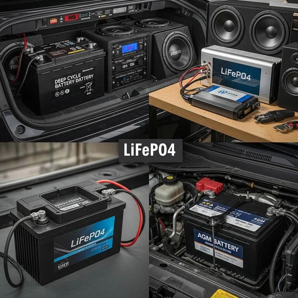
Choosing the right battery chemistry and capacity depends on use case: long runtime or repeated deep discharge favors deep cycle batteries, weight-sensitive or high-cycle applications favor LiFePO4, and compact, maintenance-free installations often use AGM. Each chemistry is a hyponym under automotive batteries and differs across attributes like usable amp-hours (Ah), depth of discharge (DoD), cycle life, weight, and charging profile. Comparing these attributes clarifies which battery suits trunk-mounted subwoofers, show systems, or mobile DJs. The table below compares Deep Cycle, LiFePO4 (lithium iron phosphate), and AGM for car audio use and makes scenario-based recommendations.
Below is a concise comparison of common car-audio battery types to guide selection.
This table helps match battery characteristics to real-world needs; next we compare these types in more depth and discuss mixing options.
How Do Deep Cycle, Lithium, and AGM Batteries Compare for Car Audio?
Deep cycle batteries deliver large usable capacity at a lower cost per Ah and tolerate sustained discharges, which is why they’re common in long-run audio setups installed in trunks or truck beds. LiFePO4 batteries offer superior cycle life, lighter weight, and deeper usable discharge—making them ideal for competitive or mobile systems—but require compatible charging or a DC-DC charger and a battery management system (BMS). AGM batteries sit between starting and deep cycle types: they’re maintenance-free, resist vibration, and handle bursts of current well but have less usable depth of discharge than LiFePO4. Comparing these trade-offs clarifies the best fit for your installation and leads to rules about mixing chemistries in a dual setup.
Can You Mix Different Battery Types and Capacities in a Dual Setup?
Mixing different battery chemistries or unequal capacities in a single system is generally discouraged because dissimilar charge acceptance and internal resistance create imbalanced charging and shortened lifespan. If mixing is unavoidable—such as adding an auxiliary AGM to an existing starting battery—you should use a proper isolator, VSR, or DC-DC charger to manage charge profiles and avoid paralleling unlike chemistries directly. Matching nominal voltages is mandatory and adding a dedicated charging device that handles LiFePO4 charging stages prevents over- or under-charging that damages batteries. These precautions protect both batteries and prepare you for choosing the isolator or VSR hardware discussed next.
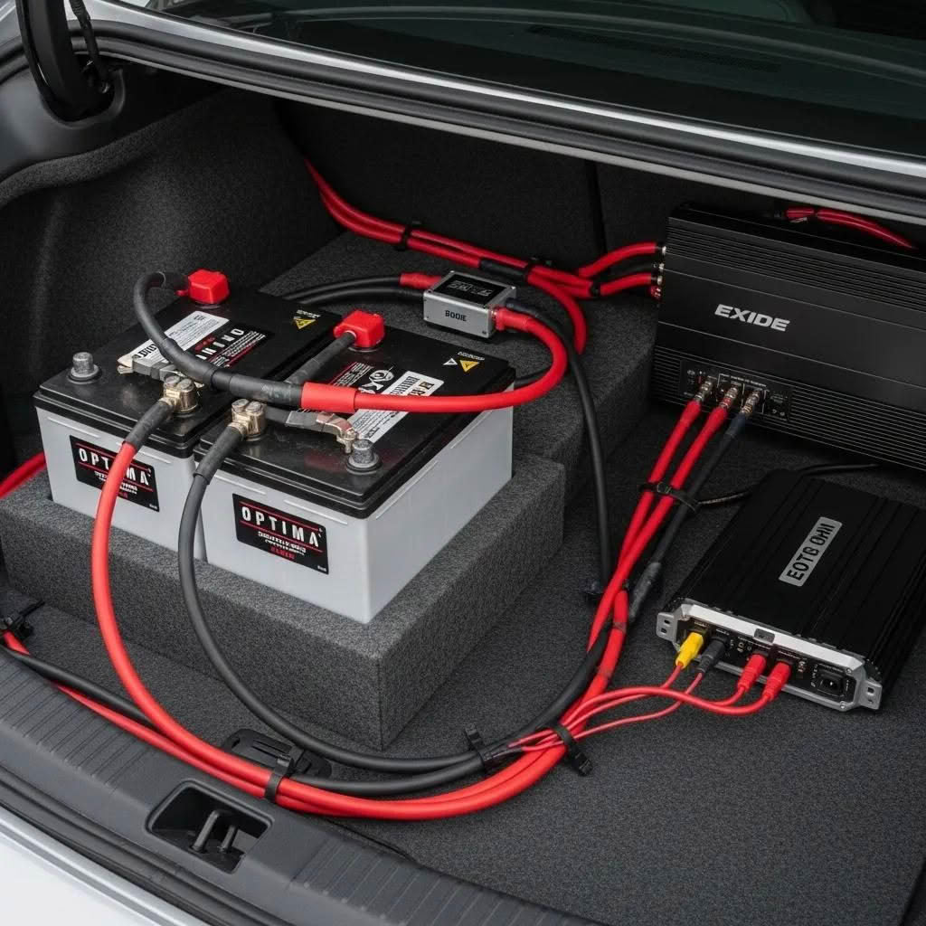
What Components Are Essential for Wiring Two Batteries in a Car Audio System?
Essential components include the auxiliary battery, battery isolator or voltage sensitive relay (VSR) or DC-DC charger, heavy-gauge positive and negative cables, properly rated fuses or ANL fuse holders, a distribution block for amplifier feeds, and secure mounting hardware. Each component is a meronym of the complete power distribution system and plays a defined role: the isolator controls charging, the fuse protects the run, and the wire gauge determines voltage drop. Below is an EAV table that lists core components, recommended ratings, and installation tips to simplify procurement and planning.
The table below lists essential components with attributes and practical tips.
This component breakdown clarifies what to buy and where to install it; next we explain isolator operation and wire/fuse sizing specifics.
How Do Battery Isolators and Voltage Sensitive Relays Work in Dual Battery Systems?
Battery isolators route alternator charge to multiple batteries while preventing one battery from discharging another when the alternator is off; smart isolators use solid-state diodes or MOSFETs to reduce voltage drop, and VSRs close a heavy-duty relay once charging voltage hits a threshold. A DC-DC charger is a hyponym of isolator solutions that actively manages charge profiles for different chemistries, especially LiFePO4, by providing multi-stage charging and isolation. When choosing, compare amp ratings, voltage thresholds, and thermal performance to ensure the isolator or charger will handle alternator output and the expected audio load. Understanding these differences guides proper wiring and helps prevent mischarging or premature battery wear, which leads into the next subsection about wire gauge and fusing.
What Wire Gauge and Fuse Sizes Are Needed for Safe Dual Battery Wiring?
Wire gauge selection is driven by expected current and cable length; for high-current amplifier mains, 1/0 AWG or 2/0 AWG is common, while smaller runs to sensors or low-current accessories may use 8–12 AWG. The fundamental rule is to size the fuse for the maximum safe current of the cable and install that fuse as close to the battery positive terminal as possible—typically within 6–18 inches—to protect against short circuits. Cable material matters: oxygen-free copper (OFC) has lower resistance than copper-clad aluminum (CCA) and reduces voltage drop; insulation should be rated for automotive temperatures. The next table provides a quick lookup pairing amplifier current demands with recommended AWG and fuse types to simplify selection.
Here is a wire-gauge and fuse sizing lookup to guide installations.
Use this table as a baseline and adjust for longer runs; next we move into the how-to installation steps that use these components and sizes.
How to Install and Wire Two Batteries for Car Audio: Step-by-Step Guide
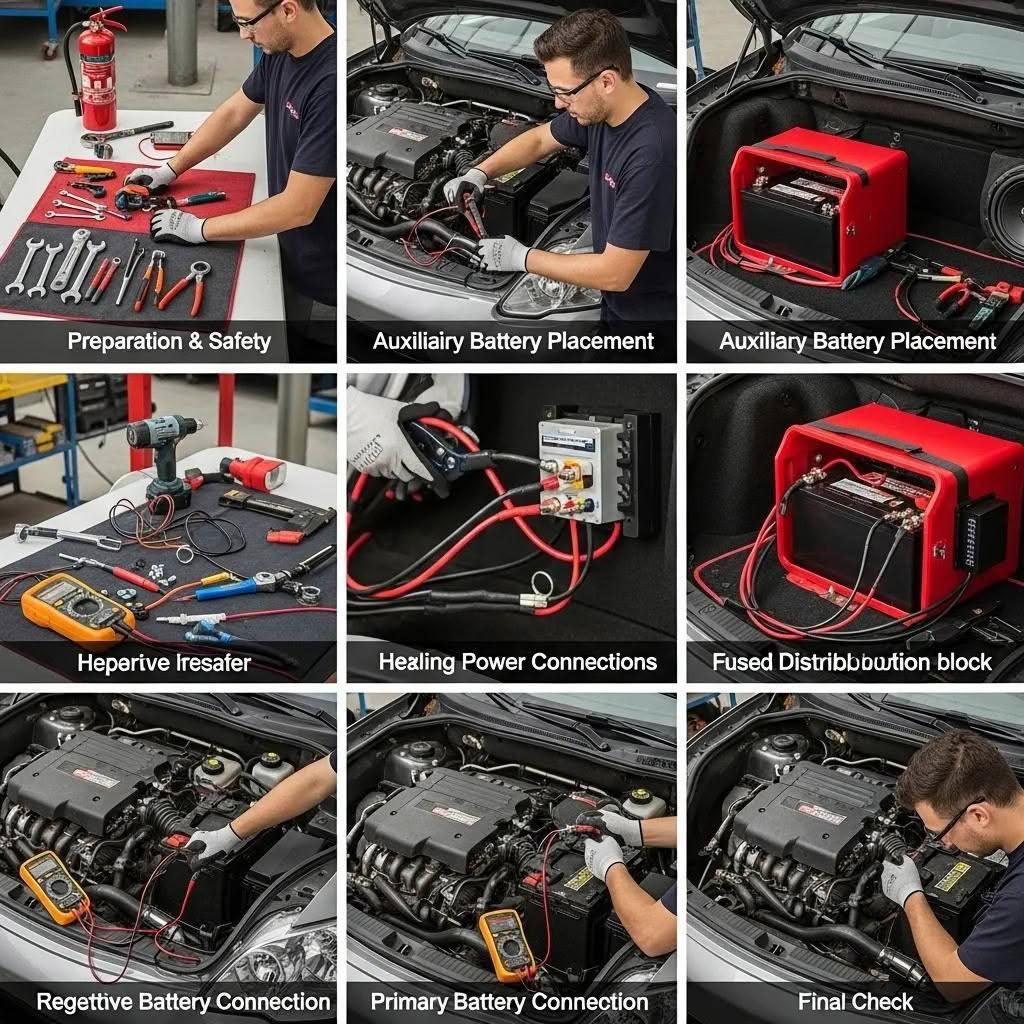
Installing two batteries requires planning battery placement, selecting secure mounting, routing heavy-gauge cables with correct fusing, and verifying proper grounding and isolator connections. Start by planning to minimize cable length between batteries and distribution blocks to reduce I * R voltage drop, and select locations with adequate ventilation for flooded batteries. The step-by-step series below walks through tools, safety checks, mounting, wiring positive and negative runs, isolator connections, and commissioning tests to guarantee a reliable system. Read each numbered step and perform multimeter checks in the final step to confirm voltages and isolator behavior.
- Plan placement and cable routing: Map battery and amplifier locations to minimize runs and keep high-current cables away from signal lines.
- Disconnect main battery and wear PPE: Always remove battery negative first and confirm no parasitic power before cutting or crimping.
- Mount the auxiliary battery: Secure in a battery box or tray using tie-downs and vibration pads; locate close to amplifier bank if possible.
- Install fuses at battery positive: Place ANL fuses within 6–18 inches of each positive terminal to protect cable runs.
- Run heavy-gauge positive and ground cables: Connect positives through isolator/charger and ground negatives with short, thick cables; implement star-grounding if needed.
- Connect isolator and distribution block: Follow isolator terminal labels (BATT/ALT/ACC) and run fused outputs to the amplifier distribution block.
- Test and commission: With engine off, measure resting voltages; start engine and verify charging voltages and VSR engagement; perform a load test while monitoring headlight dimming and voltage sag.
This numbered plan establishes a safe wiring sequence; the next subsections expand on placement, grounding, isolator hookup, and final checks.
How Do You Plan Battery Placement and Secure the Secondary Battery?
Choose battery locations that balance short cable runs, weight distribution, and accessibility. Common options include trunk mounting for subwoofer systems, under-seat or passenger-footwell mounting for compact installs, or under-hood mounting if space and heat considerations allow. Use a dedicated tray or sealed battery box for flooded or AGM types, and anchor the battery with proper tie-downs and vibration isolation pads; LiFePO4 cells often require different enclosures and ventilation considerations. Ensure the chosen site permits fuse placement close to the battery and access for periodic inspection, which leads into wiring and grounding practices covered next.
What Are the Steps to Wire Primary and Secondary Batteries with Proper Grounding?
Begin by connecting fused positive runs from each battery to the isolator or DC-DC charger, ensuring the fuse is installed within the required distance of the battery terminal. For grounding, use short, heavy gauge negative cables either bonding both negatives together with a thick jumper or using battery-to-chassis grounds that are cleaned to bare metal; remove paint and corrosion for low resistance contact. Star-grounding the amplifier distribution block to a single ground point reduces ground loop noise and improves measurement repeatability during troubleshooting. Torque all terminal connections to manufacturer specs and protect terminals from corrosion—proper grounding improves both audio fidelity and safety and sets up the isolator/instrumentation hookup discussed next.
How Do You Connect the Battery Isolator and Audio Amplifier Correctly?
Identify isolator terminals (commonly labeled BATT, ALT, and AUX) and connect the main battery positive to the alternator/BATT input and the auxiliary output to the aux battery, with the alternator or main battery feeding through the isolator so charge is routed when thresholds are met. Run a fused main positive from the aux battery to an amplifier distribution block and install individual ANL fuses per amplifier channel or per amp as required. Ground the amplifier chassis to the same grounding point used for battery negatives to avoid ground loops, and keep power and signal runs separated to reduce noise. Confirm isolator engagement at engine idle to verify the alternator is charging both banks before powering up the audio system.
Understanding how relays function in automotive systems is crucial for managing power flow, especially when dealing with multiple batteries.
12V Relays for Car Battery Systems
The relays are 12v relays since the car battery is a 12V battery. The common terminal of the relay is connected to the battery, the normally open terminal is connected to the load, and the normally closed terminal is connected to the battery.
AUTOMOBILE CONTROL SYSTEM USING VOICE COMMAND, 2016
What Final Checks and Tests Ensure a Safe and Efficient Dual Battery Setup?
Conduct commissioning checks using a digital multimeter and a simple load test to confirm system behavior. Measure resting voltage on both batteries with the engine off, then start the engine and confirm charging voltage on both terminals (typically around 13.8–14.6 V depending on vehicle charging system). Verify the isolator/VSR closes at its threshold and opens when charging voltage drops, test amplifier operation under a realistic audio load while observing headlight brightness, and inspect all fuses for correct rating and secure mounting. Confirm there are no hot terminals, loose lugs, or cable insulation chafing; once satisfied with these tests, document wiring paths and label key connections for future troubleshooting.
How Can You Optimize and Maintain Your Dual Battery Car Audio System?
Optimization and maintenance keep the dual battery system reliable and minimize voltage-related problems; regular checks include measuring battery voltage, specific gravity where applicable, cable integrity, and alternator output under load. Reducing voltage drop is primarily achieved by shortening runs where possible, upsizing AWG for high-current conductors, and performing the Big 3 electrical upgrade to lower resistance in main charging and grounding paths. Scheduled tasks such as periodic load testing, ensuring isolator and DC-DC charger firmware/settings are correct, and observing battery health metrics allow early detection of failing cells. The next subsections explain practical fixes for dimming, the specifics of the Big 3 upgrade, and a troubleshooting flow to follow when problems arise.
How Do You Prevent Voltage Drop and Headlight Dimming in Dual Battery Systems?
Prevent voltage drop by following Ohm’s law: voltage drop = current × resistance, and reduce resistance with thicker cables (lower AWG), shorter cable runs, and high-quality crimped terminations. Use distribution blocks near the amplifier bank to shorten individual runs and minimize connection points that add resistance, and separate high-current cables from signal runs to avoid interference. If headlights still dim under heavy audio load, consider alternator upgrades or a high-output charging solution and verify that cable and fuse sizing match the actual measured currents. These measures reduce losses, improve charging efficiency, and set the stage for the Big 3 upgrade explained next.
- Quick measures to reduce voltage drop:
Shorten cable lengths for high-current runs.
Increase conductor size to lower resistance.
Improve terminations and minimize connection points.
These actions produce measurable improvements in system voltage and audio performance, which ties directly into the Big 3 upgrade mechanics.
When planning any car audio system, it’s essential to consider how your existing electrical system can support the new gear.
Car Audio System Planning and Electrical Considerations
In this chapter, I set you on the road to a great car audio system: I cover how to decide what kind of system you really need and want, how to factor in your budget, and how to make the most of your existing car’s electrical system to power your new audio gear.
Car audio for dummies, 2008
What Is the “Big 3” Electrical Upgrade and How Does It Improve Your Setup?
The Big 3 upgrade replaces three key factory conductors with thicker wires: (1) chassis ground to engine block, (2) alternator positive to battery positive, and (3) engine block ground back to chassis or battery negative. Upgrading these three conductors—commonly to 1/0 AWG or 2/0 AWG depending on demand—reduces overall system resistance, improving alternator charging efficiency and reducing voltage drop during high-load events. The result is higher available voltage at the amplifier, reduced headlight dimming, and improved alternator performance under sustained audio loads. Implementing the Big 3 is a high-leverage optimization typically paired with proper fusing and grounding practices discussed earlier.
How Do You Troubleshoot Common Dual Battery Wiring Issues?
Troubleshooting follows a methodical path: begin with a visual inspection, check all fuse integrity, verify terminal tightness, then measure voltages at rest and under load to isolate where drops occur. If the auxiliary battery is not charging, test isolator/VSR engagement or DC-DC charger output and confirm alternator voltage at the main battery. For persistent noise, examine ground integrity and separate signal runs from power runs; test for ground loops by temporarily disconnecting grounds at known points. A systematic flow—visual → fuses → voltages → isolator/charger → alternator—helps you find root causes quickly and safely.
What Safety Precautions Are Critical When Wiring Two Batteries for Car Audio?
Safety is paramount when working with dual-battery systems: protect all positive runs with correctly rated fuses close to the battery terminal, disconnect batteries before any work, wear protective equipment, and secure batteries to prevent movement that could damage cables or cause shorts. Short circuits on heavy-gauge cables can produce catastrophic heat and fire; placing ANL fuses within 6–18 inches of the battery positive terminal ensures the cable is protected against conductor faults. Additionally, mounting flooded batteries in ventilated boxes, using terminal covers, and routing cables away from sharp edges minimizes hazard potential. The following subsections detail why fusing is essential and how to establish reliable ground connections.
Why Is Proper Fusing Near Battery Terminals Essential?
Fuses are the system’s primary defense against catastrophic short-circuit currents; they interrupt excessive current before cables overheat and insulation fails. Installing the fuse within the recommended 6–18 inch distance of the battery positive terminal ensures that the unprotected length of conductor is minimized and that any short downstream will blow the fuse instead of allowing the wire to act as a fuse. Choose ANL or equivalent high-interrupt-rating fuse types for high-current runs and verify the fuse’s amp rating matches the cable’s safe continuous current. Proper fusing protects vehicles, equipment, and people, and it’s the first safety measure to implement before powering up a new installation.
- Why to fuse near the battery:
Minimizes unprotected cable length against shorts.
Ensures the fuse interrupts large fault currents safely.
Protects cable insulation and prevents fires.
These rules are foundational; the last subsection explains establishing reliable grounds that complement proper fusing.
How Should You Establish Reliable Ground Connections to Avoid Electrical Issues?
Reliable grounding requires short, heavy-gauge negative cables with clean metal-to-metal contact; remove paint and corrosion at chassis tie points, use star-grounding for audio systems when possible, and bond both battery negatives if the design calls for it. Avoid daisy-chained grounds for amplifiers; instead, route each amplifier ground to a single common point to minimize ground loops and audible noise. Use lock washers and appropriate torque to prevent loosening under vibration, and periodically inspect grounds for oxidation or loosened hardware as part of maintenance. Proper grounding reduces noise, ensures accurate charging behavior, and completes a safe electrical system ready for reliable audio performance.
- Grounding checklist:
Use the shortest possible negative runs in heavy gauge.
Clean contact surfaces to bare metal for secure bonds.
Implement star-grounding or single-point grounding for audio equipment.