Evolution Lithium Car Audio Guide
DIY Car Audio Lithium Battery Bank: Planning and Safety Checks
A DIY car audio lithium battery bank is an electrical-system design project, not simply a set of cells joined together. Use these checks to decide whether a custom build is appropriate before buying cells, cable, fuses or charging hardware.
Is a DIY Car Audio Lithium Battery Bank Right for You?
DIY is most appropriate for an experienced installer who can verify cell identity and history, follow the cell manufacturer’s specifications, make reliable busbar and cable connections, protect every positive conductor and commission the system safely.
Use a qualified installer or a proven assembled bank if you cannot confirm the cells’ condition, do not have suitable test equipment, are unsure how the vehicle regulates charging voltage or cannot produce repeatable low-resistance connections. One loose terminal, polarity error or unfused conductor can create far more cost and risk than the saving from assembling the bank yourself.
Choose the Battery Chemistry for Your Use Case
AGM, LiFePO4 and SCiB LTO are not interchangeable drop-in choices. Each chemistry has different cell voltages, charging limits, current capability and installation requirements. The exact cell model matters, so do not transfer a voltage or current figure from one chemistry or cell family to another.
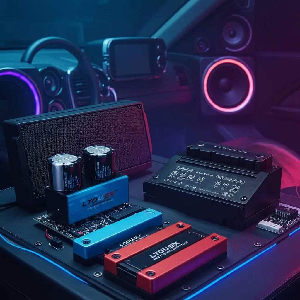
Evolution Lithium primarily works with Toshiba SCiB LTO for demanding car audio systems. Toshiba describes SCiB as a lithium-titanium-oxide technology designed for rapid charging, high input and output, long life and a wide operating range. Those are cell-family characteristics, not permission to exceed the published limits of a particular cell or finished bank. See Toshiba’s official SCiB overview and compare available SCiB car audio battery banks.
Size the Bank From Amplifier Current and Alternator Support
Do not size a bank from amplifier advertising wattage alone. Start with manufacturer-rated RMS output, the planned system voltage and a realistic efficiency assumption. Then account for programme material, duty cycle, impedance rise, clipping risk, cable resistance and the alternator’s usable contribution.
This is a planning estimate, not the battery-only current and not a fuse-size recommendation. Engine-off listening needs more stored energy than a short demo with strong charging support. A larger bank stores more energy, but it does not create alternator output. If average demand exceeds what the alternator can replace, extra capacity only delays depletion.
Use the car audio lithium battery sizing guide to compare amplifier demand, charging support and intended use.
Measure Charging Voltage Before Selecting Cells
Record charging voltage after a cold start, when the vehicle is warm, at idle and at raised engine speed. Repeat the measurements with normal vehicle loads operating. Check whether smart charging or voltage control changes alternator output during driving.
Measure at the starting battery and at the proposed rear-bank location so front-to-rear cable loss is visible. A resting-voltage reading does not show how the system behaves while the amplifiers are drawing current. These measurements determine whether the planned chemistry and series count are compatible and whether regulation, alternator or cable work is required first.
Plan a Boot or Rear-Cabin Installation
Do not install a lithium car audio bank under the bonnet. Mount it in the boot or rear cabin, away from sustained engine heat, road contamination and direct moisture. The enclosure or bracket must restrain the bank in every direction and keep passengers, luggage and loose metal objects away from terminals and busbars.
Plan service access, cable entry points, terminal clearance, ventilation where required and protection from crash loads before drilling or cutting cable. Mechanical restraint is part of the electrical design because movement can loosen connections, damage insulation and turn resistance into heat under high current.
Design Fusing Before Routing Cable
Every positive conductor must be protected for the smallest cable or component that the fuse is intended to protect. Battery burst capability and amplifier marketing power do not establish the correct fuse rating.
A rear bank connected to the front electrical system creates two energised ends of the long positive cable. Protect the cable close to the starting-battery end and again close to the rear-bank end. Keep unprotected cable length as short as practical, use grommets at metal penetrations and route the cable away from sharp edges, heat, moving parts, fuel lines and airbag equipment. Review the dual-battery wiring guide before finalising the layout.
Treat Connections and Grounds as Critical Components
High-current systems quickly expose weak crimps, undersized lugs, loose fasteners, poor fuse holders and painted grounding points. Use conductors, lugs, ferrules and busbars that suit the current and installation method. Prepare chassis connections to clean structural metal, use secure hardware and protect the completed joint from corrosion.
The negative path needs the same planning as the positive path. After installation, measure voltage drop across both routes while current is flowing. A hot terminal or an unexpectedly large voltage difference between measurement points indicates resistance that must be corrected before increasing the load.
Use an Active Balancer Correctly
An active balancer can help keep series cell groups aligned, but it cannot make unknown, damaged or mismatched cells suitable for use. Confirm that the balancer supports the exact series count and expected cell-voltage range. Its sense wiring must be connected in the specified order, insulated and protected from abrasion.
Measure every cell group independently before connecting the active balancer, then observe the bank during controlled charging and loading. If one group repeatedly separates from the others, investigate the cells and connections instead of assuming more balancing current will fix the cause.
Commission the Battery Bank in Controlled Steps
- Inspect cell condition, polarity, insulation, fastener security and terminal clearance.
- Confirm individual cell-group voltage and total bank voltage with a suitable meter.
- Use a purpose-built pre-charge method before the final connection where amplifier input capacitors can create heavy inrush current.
- Begin with low charging and load levels while monitoring voltage and connection temperature.
- Increase load gradually and record voltage at the front system, rear bank and amplifier terminals.
- Stop if a cell group separates, a connection heats, a fuse holder discolours or charging voltage leaves the approved range.
Common DIY Lithium Battery Bank Mistakes
- Buying cells without verifiable identity, condition or history.
- Mixing cell models, capacities or states of health.
- Copying a charging target from a different chemistry or series count.
- Relying on amp hours as the only sizing measure.
- Protecting only one end of a cable connected between two batteries.
- Mounting lithium under the bonnet.
- Treating extra battery capacity as a substitute for alternator output.
- Skipping voltage-drop and temperature checks under load.
When an Assembled Battery Bank Is Better
Choose a proven assembled bank when you want known cell matching, established hardware, a defined active-balancing approach and support for the intended application. This is usually the better route for a daily driver, a time-critical installation or any build where the installer cannot document every design limit.
A custom bank may suit unusual packaging or advanced competition requirements, but only when the builder can document the cells, connections, protection, charging strategy and commissioning results. The safest choice is the system that can be verified, inspected and maintained after the vehicle returns to normal use.
Next: Follow the Detailed Installation Guide
If the planning checks show that a custom lithium bank is appropriate, continue with the step-by-step second-battery installation guide. Confirm the cable sizes, fuse ratings, charging limits and active-balancer connection order for the exact components before energising the system.