
Proper Grounding Techniques for Car Audio
A Complete Guide to Eliminate Noise and Enhance Sound Quality
A solid chassis ground is the foundation of a quiet, reliable car audio system. Good grounding creates a low-resistance electrical reference between your audio gear and the vehicle body, stabilising voltages and stopping unwanted noise. This guide walks through why grounding matters, how bad grounds create hum and alternator whine, and the practical steps installers use to achieve a low-resistance chassis ground that improves fidelity and reliability. You’ll learn how to pick the best grounding points, prepare bare metal contact, choose the correct ground wire gauge, and verify connections with multimeter tests. We also map troubleshooting workflows for ground loops and alternator-induced noise, and show how modern LTO (lithium titanate oxide) SCiB batteries reduce voltage sag and stabilise supply under heavy loads. Finally, we highlight Evolution Lithium LTO options and accessories that support a robust grounding topology—from compact systems to high-output builds.
Why Is Proper Grounding Essential for Car Audio Systems?
Proper grounding gives your system a single, low-resistance return path and a stable reference voltage. When the audio system is tied to clean chassis metal, ground impedance drops and stray currents that cause ground loops or alternator whine are limited. Low-resistance grounds also reduce thermal stress and voltage swings during high-current peaks, helping amplifiers stay reliable and perform at rated output. In short: grounding is the first practical step in any noise-reduction strategy—and it must be paired with proper power delivery for high-performance installs.
The next section shows the audible and electrical signs of poor grounding, then explains how consistent grounding measurably improves signal-to-noise ratio and system uptime.
What Happens When Car Audio Grounding Is Poor?
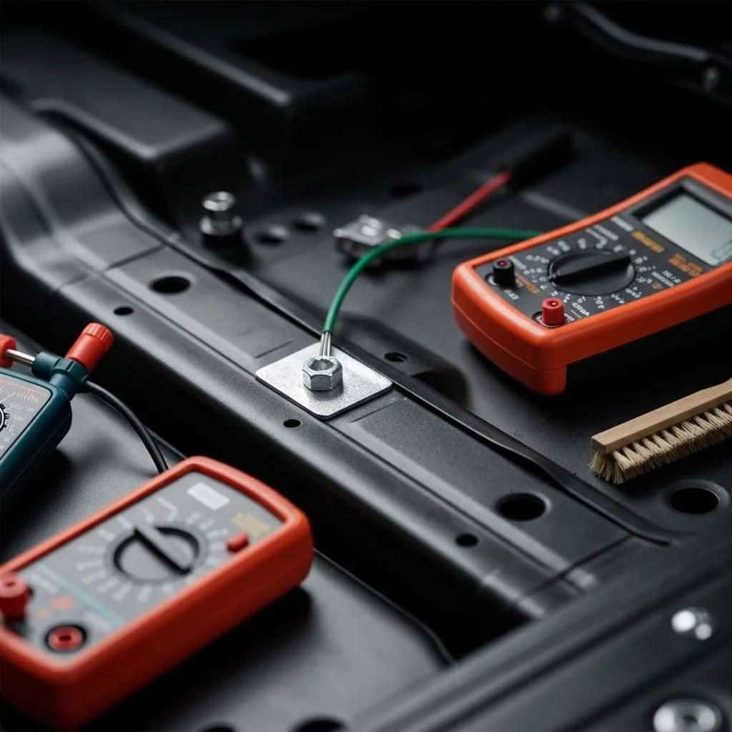
Poor grounding usually shows up as hum, buzzing, intermittent amp shutdowns and hotter-than-normal power wiring. High-resistance grounds let amplifier chassis and source grounds sit at different potentials, which drives ground loop currents through RCA shields or input stages and makes the noise audible. You can detect poor grounds with simple continuity and resistance checks: a good chassis ground should read close to 0 Ω and show only millivolt differences under load in a multimeter ground test. Fixing grounding problems early prevents component damage and cuts diagnostic time during installs.
Knowing these failure modes leads directly into how correct grounding improves audio clarity and system reliability under dynamic loads.
How Does Proper Grounding Improve Sound Quality and System Reliability?
Proper grounding lowers the noise floor by providing a stable reference for amplifier inputs and outputs, improving effective signal-to-noise ratio and delivering tighter bass and clearer mids. Mechanically secure, low-resistance connections also reduce heat buildup in terminals and wiring because current follows the intended path instead of leaking across poor contacts. In practice, correct grounding reduces susceptibility to alternator modulation and helps amplifiers hold output during transients without protective dropouts. Those gains translate into audible improvements and fewer long-term failures.
Because grounding and power interact, the next section covers how to pick the best physical grounding point in a vehicle.
How Do You Choose the Best Grounding Point for Your Car Audio?

Pick a point that’s structurally tied to the chassis and close to the amplifier to keep loop length short and ground impedance low. Best candidates are solid bolts on unpainted sheet metal or chassis brackets where you get direct metal-to-metal contact and a dependable mechanical fastening. Avoid flexible or isolated parts that can add intermittent contact and resistance. Choosing the right point up front makes wiring, testing and noise reduction much more predictable.
Below we list common grounding locations and the surfaces to avoid or prepare if a perfect spot isn’t available.
Where Are the Ideal Grounding Locations in a Vehicle?
Installers commonly use factory structural bolts, seat-bolt locations, trunk mounting points or a dedicated chassis ground stud tied straight to the body. These spots offer thicker metal, a short return path to the vehicle’s negative bus, and a secure anchor for ring terminals and star washers. Keep the ground lead as short and direct as the power lead to balance impedances and lower the risk of forming loops through other components. For multi-amp systems, a centrally mounted ground distribution block helps preserve single-point grounding discipline.
Picking one of these locations reduces ground loop length and simplifies troubleshooting—vital when systems run at higher output.
What Surfaces Should You Avoid When Grounding Car Audio Components?
Don’t use painted panels, plastic, or corroded and undercoated areas—coatings and corrosion electrically isolate the terminal and raise contact resistance. Undercoating, seam-sealers and thick paint often cause intermittent noise as they break or flex. If you can’t find bare metal, prepare the surface: remove coatings to bright metal with a wire brush or fine abrasive, make the connection, then apply a corrosion inhibitor sparingly around the terminal (not between the mating surfaces). Use corrosion-resistant terminals and inspect periodically to keep resistance low over time.
Surface choice and prep affect both immediate noise and long-term connection stability; next we walk through step-by-step grounding techniques.
What Are the Step-by-Step Proper Grounding Techniques for Car Audio?
Below is a practical, installer-focused workflow: disconnect the battery, clean and prepare the grounding surface, match ground wire AWG to amplifier current, crimp or solder quality ring terminals, and torque the terminal to a solid mechanical connection—using a star washer where appropriate. Route and secure cables with ties, then verify continuity and voltage drop under load with a multimeter. Follow these steps in order to establish a low-resistance chassis ground that minimises noise and improves safety.
Tools and checks to have ready for a professional grounding job:
- Disconnect Battery: Remove the negative terminal to prevent shorts while you work.
- Surface Prep Tools: Wire brush, fine sandpaper and rust inhibitor to expose clean metal.
- Crimp and Torque Tools: Quality crimper, heat-shrink and a torque driver for secure terminations.
- Testing Tools: Multimeter for continuity and voltage-drop checks under simulated load.
Follow this workflow, then consult the AWG recommendations to match ground gauge to expected current.
How Do You Prepare the Grounding Surface for Optimal Connection?
Start by disconnecting the battery, then expose bright metal using a wire brush, light sanding or an abrasive pad. Remove rust or oxidation with a converter where needed, and confirm the chosen bolt or stud ties into structural metal rather than a thin skin panel. After tightening the terminal, protect the surrounding area with a corrosion inhibitor or a small amount of dielectric grease—but don’t coat the actual mating surface. Good surface prep lowers contact resistance and extends service intervals.
Proper prep also improves multimeter readings during the verification steps covered next.
How Do You Select and Install the Right Ground Wire Gauge?
Match the ground conductor to the amplifier’s current draw and the vehicle’s power cable to avoid a bottleneck in the return path. The table below shows common AWG sizes and typical continuous currents to help choose a safe gauge for common system power levels.
Wire sizing should equal or exceed the power conductor capacity; oxygen-free copper (OFC) is preferred for lower resistance and long-term reliability. Route the ground wire in a short, straight run, protect it with grommets where it passes metal, and prevent chafing to keep resistance low. Correct material choice and routing ensure the ground path doesn’t become the weak link during heavy transients.
These rules feed into the mechanical fastening and testing methods explained next.
How Do You Secure and Test Your Ground Connection?
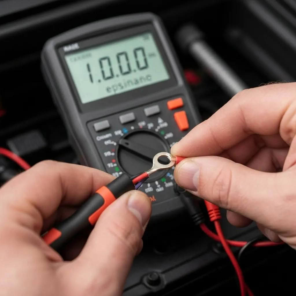
Use a correctly sized ring terminal that’s crimped or soldered, a hardened star washer to bite into clean metal, and a torque-specified bolt or factory stud to hold consistent compression. After fastening, test continuity with a multimeter—values should be near 0 Ω—and measure voltage drop under simulated load; healthy grounds usually show only millivolts. If readings are high, recheck surface prep, terminal seating and wire integrity, then re-torque and retest until values are acceptable. Finish by dressing and securing cables to prevent movement and wear.
These securement and verification steps complete the installation workflow and prepare you to diagnose any remaining issues.
How Can You Troubleshoot and Eliminate Common Car Audio Grounding Issues?
Use a step-by-step diagnostic sequence: first determine whether noise is present with the engine off (likely a ground loop or RCA issue) or only with the engine running (suggests alternator whine or voltage modulation). Employ multimeter ground tests and signal tracing: disconnect RCAs, tap sources, and temporarily ground the head unit to see whether the noise follows power or inputs. If problems persist, check for shared grounds across devices—consider single-point grounding or ground loop isolators where topology prevents an ideal layout. Systematic isolation stops unnecessary part swaps and reveals whether wiring, grounding, or power-source instability is at fault.
The table below maps common symptoms to probable causes and tested fixes to speed repairs.
Linking what you hear to targeted electrical actions speeds repairs. The following subsections go deeper into ground loops and alternator whine remedies.
What Causes Ground Loop Noise and How Do You Fix It?
Ground loops form when multiple ground paths create a closed circuit between audio components and small voltage differences circulate, injecting hum into the signal chain. To confirm a loop, disconnect signal inputs one at a time—if the hum stops when an RCA is unplugged, the loop is likely in the signal path. Fixes include consolidating grounds to a single chassis reference, keeping signal cables away from power runs, and using ground loop isolators or isolation transformers when routing constraints prevent ideal topology. These measures stop the circulating currents that create audible hum without compromising system function.
Fixing ground loops is often the first step before tackling alternator whine.
How Do You Prevent and Reduce Alternator Whine in Car Audio Systems?
Alternator whine varies with engine RPM and is caused by supply voltage modulation under load; it usually couples into signal grounds or RCA runs. Start by improving the electrical return: shorten ground leads, use heavier gauge power and ground wiring, and verify alternator and battery grounds are solid. A Big 3 wiring upgrade reduces voltage drop between alternator, battery and chassis; adding a stabilising battery bank can absorb transients. If wiring work doesn’t eliminate the whine, use targeted filters and shield RCA runs to reduce residual coupling into the audio chain.
When power stability limits performance, high-performance batteries can be a complementary solution—explained next.
How Do LTO Lithium Batteries Enhance Proper Grounding and Electrical Stability?
LTO (lithium titanate oxide) SCiB batteries improve electrical stability with very low internal resistance, high discharge rates and fast recharge capability—characteristics that reduce voltage sag during extreme amplifier transients. That stability lowers the amplitude of supply modulation that can propagate through ground and signal references, meaning a properly grounded system benefits more from a stiff power source. The table below compares LTO to AGM and lead-acid so you can see why LTO often outperforms conventional options in high-demand audio setups.
What Are the Benefits of LTO Batteries for Voltage Stability and Noise Reduction?
LTO batteries hold voltage under heavy transient load because of low internal resistance and strong discharge capability, keeping the system reference stable during musical peaks. Rapid recharge in SCiB cells means amplifier draw-downs are replenished quickly, reducing the duration of any sag that could couple into signal grounds. Their long cycle life and thermal resilience also make LTO banks reliable for repeated deep cycling common in demanding audio setups. For installers this means fewer false positives during troubleshooting and less reliance on large passive capacitance to hold voltage during peaks.
Pairing a stiff power source with a low-resistance ground multiplies the benefit: the battery reduces source variability while proper grounding eliminates reference differentials.
How Does Combining LTO Batteries with Proper Grounding Improve Audio Performance?
Using LTO battery banks with careful grounding topology gives a compound effect: the stiff power source reduces transient-induced reference shifts and the low-resistance chassis ground removes local potential differences that can become audible. Practically, mount the LTO bank close to the amplifier cluster, keep power and ground runs short, and tie the battery negative to the same chassis grounding point used by the amp to avoid separate return paths. This integrated approach reduces alternator whine, tightens bass by preventing sag, and lowers the chance of ground-related noise as system power grows. Consider LTO upgrades when wiring and grounding improvements alone don’t stop RPM-correlated noise.
What Evolution Lithium Products Support Optimal Car Audio Grounding?
Evolution Lithium supplies LTO SCiB battery banks and support accessories engineered for high-performance car audio. These products complement good grounding by delivering stable voltage and high transient current capacity. Our range covers small modules for compact systems through larger banks for high-output installs, plus fuse holders, quality cables and distribution hardware installers need for a robust grounding topology. Choose the right product to match continuous and peak current demands so Evolution Lithium solutions work together with best-practice grounding to create a noise-resistant electrical architecture.
Which LTO Lithium Batteries Are Best for High-Performance Car Audio Systems?
Pick LTO capacity based on expected amplifier peak draw and duty cycle: small SCiB modules suit compact systems with modest transients, mid-range banks match multi-amp mid-power setups, and larger banks are for competition-level, high-output installations. Parallel configurations increase available current while preserving low internal resistance; place battery banks close to the amp cluster to shorten power and ground runs. Evolution Lithium builds custom banks from genuine SCiB cells so you can match capacity and form factor to vehicle platform and system demands.
When integrating a bank, follow grounding and Big 3 wiring best practices so the battery’s stability directly reduces noise and sag rather than introducing separate return paths that create loops.
What Accessories Help Ensure a Reliable Grounding Setup?
Reliable grounding needs the right accessories: OFC ground cables sized to your power conductors, properly sized ring terminals and star washers for low contact resistance, and sturdy fuse holders and distribution blocks to manage current safely. Corrosion-resistant terminals and heat-shrink-insulated crimps preserve low resistance over time and protect connections from vibration and moisture. Evolution Lithium offers cabling, fuse holders and distribution hardware matched to LTO banks to help installers build a unified power and grounding topology. Regular inspection and maintenance of these parts keeps the grounding system low-resistance and noise-free for the life of the install.
Following these accessory recommendations completes the path from technique to a stable, low-noise car audio system supported by modern LTO power solutions.
Frequently Asked Questions
1. What are the signs of a poor grounding connection in a car audio system?
Common signs include audible hum or buzz, intermittent amplifier shutdowns and unusually hot power wiring. These stem from voltage differentials and high resistance that introduce noise into the signal. A quick multimeter check—continuity near 0 Ω and low millivolt differences under load—will confirm a good ground. Address problems early to avoid further component damage and time-consuming diagnostics.
2. How can I improve grounding if I have multiple amplifiers in my car audio system?
Use a ground distribution block to keep a single-point grounding discipline. Ground all amplifiers to the same solid chassis point—ideally a structural bolt or stud—and keep ground runs short. This reduces loop lengths and makes troubleshooting simpler while preserving low resistance across the system.
3. What tools are essential for testing ground connections in car audio installations?
Key tools are a reliable multimeter for continuity and voltage-drop checks, a wire brush or sandpaper for surface prep, a torque driver for consistent bolt compression, and a quality crimper with heat-shrink for terminations. These tools ensure connections are mechanically and electrically sound.
4. How does the choice of ground wire gauge affect audio performance?
Ground wire gauge matters because the return path must handle the amplifier’s current without added resistance. Choose a ground that matches or exceeds the power conductor capacity to avoid bottlenecks that cause voltage sag and noise. Follow AWG recommendations based on expected current draw for the best results.
5. Can grounding issues affect the lifespan of car audio components?
Yes. Poor grounding increases thermal stress and voltage fluctuation, which can shorten component life and cause premature failures. A solid, low-resistance ground protects equipment and improves longevity—regular checks and maintenance help prevent long-term deterioration.
6. What role do LTO batteries play in enhancing grounding stability?
LTO (lithium titanate oxide) batteries support grounding stability by offering low internal resistance and high discharge rates, which reduce voltage sag during heavy transient demands. That steadier supply helps keep system reference voltage consistent and lowers noise potential when combined with proper grounding.
7. How often should I inspect my car audio grounding connections?
Inspect grounding connections at least annually, or sooner if you notice noise or performance changes. During checks, make sure terminals are clean, tight and free of corrosion. Routine inspection and maintenance keep the system performing reliably.
Conclusion
Proper grounding is one of the simplest, most effective upgrades you can make for cleaner sound and greater system reliability. By choosing the right contact points, preparing surfaces correctly, sizing and installing ground cables properly, and verifying connections with a multimeter, you dramatically reduce noise and protect your equipment. Pairing a low-resistance ground with Evolution Lithium LTO banks multiplies the benefit—less sag, fewer voltage-related artifacts and a tighter, more consistent performance. Ready to improve your system? Review our LTO options and grounding accessories to find the right solution for your build.