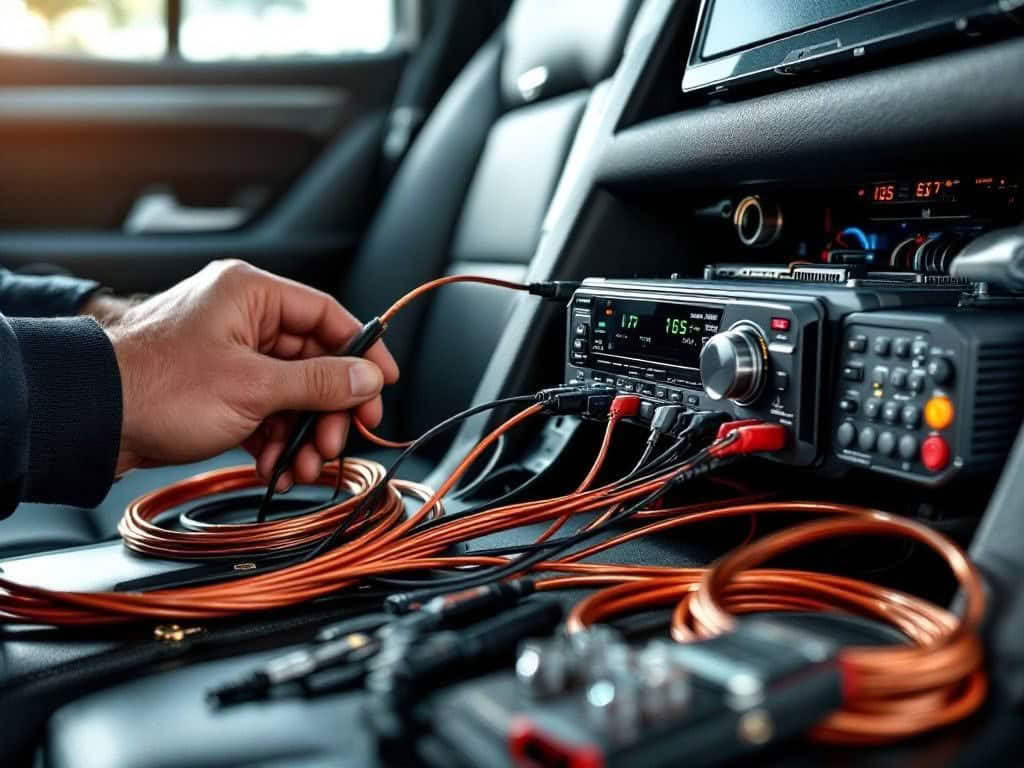
A rear lithium bank needs a secure mounting system, guarded terminals, protected cables and charging that suits the bank and vehicle. Placing it near the amplifiers can shorten their supply path, but the front-to-rear charging cable still needs careful design. This guide covers the installation decisions to confirm with your installer before connecting a high-current car audio bank.
Confirm the Bank and Electrical Plan First

Record the exact cell model, series and parallel configuration, usable capacity, approved current limits and charging instructions. Add the amplifiers’ RMS ratings at their intended impedance, then account for efficiency, actual voltage, alternator contribution and listening duration. Amplifier output watts are not the same as battery input watts.
Use our battery and alternator sizing guide for that budget. More Ah does not automatically provide the required discharge current, and a high-current bank cannot replace an ongoing charging deficit.
Draw every source, charging device, battery, cable, fuse, disconnect and amplifier branch. The plan should identify which sources can energise each cable during normal use and during a fault. Agree the isolation procedure before installation starts.
Choose a Protected Boot Location
Install lithium banks in the rear cabin or boot, never under the bonnet. Choose a dry position away from leaks, exhaust heat and moving seat mechanisms. Allow the clearances and mounting orientation specified for the supplied bank, with access to terminals, fuse holders and inspection points.
Keep luggage and tools clear of electrical hardware. A false floor or enclosure must provide room for cable bends and heat dissipation without trapping the bank against warm amplifiers. Do not assume a sealed box, extra fan or particular enclosure material is required for every bank; base those choices on temperature limits and the actual layout.
Restrain the Bank and Cover Live Parts

Use a tray and restraint system appropriate to the bank’s mass and vehicle structure. It must resist movement during braking, cornering and a collision; trim panels, carpet, loose straps and an amplifier board alone are not evidence of adequate restraint. Have suitable attachment points and any required reinforcement assessed before drilling.
Check below the proposed holes for fuel lines, brake lines, wiring and other vehicle equipment. Hold-downs must restrain the assembly without crushing cells, distorting its enclosure or loading terminal studs. Support cables independently so their weight and movement do not pull on the terminals.
Fit durable insulating covers over terminals, exposed busbars and positive distribution points. Keep metal restraints clear of live parts. Mechanical mounting and electrical grounding are separate jobs: do not strip paint from the whole tray area or assume the battery case should be electrically bonded to the chassis.
Isolate Every Source Before Wiring
Stop the engine, switch off loads and disconnect external charging equipment. Follow the vehicle and equipment instructions to isolate the starter battery, rear bank, any additional banks and other charging sources. Switching the head unit off or disconnecting only the front battery does not make a multi-battery circuit safe.
Battery terminals remain live after the bank is disconnected. Cover them, remove jewellery and use insulated tools. Confirm the wiring you will work on is de-energised with a suitable meter in DC-voltage mode. Never place a meter in current mode across a battery.
Use a disconnect with suitable DC voltage, current and switching ratings. Follow the approved shutdown sequence; do not use an arbitrary switch operation to disconnect a running alternator. Leave final energising to the installer after the complete circuit has been inspected.
Size and Route Both Current Paths

There is no cable gauge that becomes universally correct above a particular amplifier wattage. Select conductors for expected current, total route length, insulation rating, ambient temperature, bundling and acceptable voltage drop. Include the negative return path in the design.
Use correctly sized lugs and a compatible crimping die and tool. Follow the hardware manufacturer’s terminal torque and stacking instructions. Strain relief and insulating boots should protect the joint without hiding a poor crimp.
Route cables away from sharp edges, seat rails, hinges and hot components. Use suitable grommets or bulkhead fittings through metal and secure the cable along its route. Protect any section exposed beneath the vehicle. Choose ground points for an adequate current path and verify them under load; a convenient bolt is not automatically a suitable ground.
Fuse Each Battery Source and Cable Branch
A cable joining front and rear batteries can receive fault current from either end. Fit source protection close to each battery positive connection, minimising the unprotected length. Protect amplifier branches according to their individual cable and equipment limits. A large main fuse does not automatically protect a smaller downstream wire.
Select the fuse and holder as an assembly. Check continuous current capability, time-current behaviour, DC voltage rating and interrupt rating. The interrupt rating is the fault current the fuse can safely break; it must suit the prospective short-circuit current of the bank at the system voltage. It is different from the current printed as the fuse’s normal rating.
Do not assume any ANL, MEGA or other fuse format is adequate simply because it fits. Verify the exact manufacturer’s data and the installation design. Victron’s DC wiring reference explains these separate fuse ratings. Never increase a fuse rating to conceal repeated opening without finding the cause.
Match Charging to the Bank and Vehicle
Confirm Voltage Compatibility
For applicable Evolution Lithium 6S SCiB LTO banks, the preferred daily charging range is approximately 15.6–15.9V, subject to the instructions supplied with the bank. The 16.8V absolute bank ceiling is not a daily charge target. Individual cells must also remain within their specified limits; an acceptable total voltage does not prove every cell is within range.
Before changing regulation, verify the limits of every connected amplifier, head unit, DSP, starter battery and vehicle component. Do not directly parallel mismatched batteries and expect their voltages to settle safely. Use a charging arrangement approved for the exact combination.
Separate Isolation, Charging and Balancing
A relay or isolator connects or separates a current path. It does not by itself provide a suitable charging profile or regulate charging current. The Victron Cyrix-ct manual, for example, describes a relay that joins battery banks according to voltage. That function is different from controlled charging.
A DC-to-DC charger must support the required output voltage, current and charging settings; a generic lithium mode may be unsuitable for 6S LTO. Its rated output also limits how quickly it replaces energy used by the audio system. Check alternator loading and recovery time in the overall design.
An active balancer equalises cell voltage. It does not replace charging-current regulation or provide an automatic overvoltage, undervoltage or fault cutoff unless separate, specifically documented equipment performs those functions. Confirm what is actually fitted; do not assume automatic shutdowns, Bluetooth monitoring or built-in telemetry.
Our front battery and rear lithium wiring guide covers those system-planning distinctions.
Commission the Installation Gradually

- With sources isolated, inspect restraints, guards, cable protection, fuse specifications and terminal torque.
- Check polarity and source voltages before connection. Follow any specified pre-charge procedure rather than accepting a large connection spark as normal.
- Energise in the approved sequence with audio loads off. Check bank and individual cell voltages, then confirm charging stays within the supplied limits.
- Apply a short, controlled audio load. Compare bank and amplifier voltage under the same conditions, and inspect connections for abnormal heating.
- Repeat at the intended engine speed and after warm-up. Stop if a cell diverges, voltage leaves its approved range, hardware heats abnormally or equipment enters protection.
Use the voltage-drop measurement guide to distinguish cable losses from a supply shortfall. Save the readings, circuit drawing, component ratings and charging settings for future checks.
Keep the Installation Accessible for Inspection
Check for loose restraints, water ingress, damaged insulation and disturbed guards after initial use, heavy sessions or changes to the boot layout. Follow the supplied inspection and storage instructions. Tighten terminals only to their specified torque; repeated uncontrolled tightening can damage hardware.
Contact Evolution Lithium with your vehicle, amplifier ratings, alternator details and proposed boot layout before choosing the final bank and charging arrangement.